VU Channel A or B: Input,
Output, PEAK Limiter,
TEMP Limiter
Level in dB
X
Set level reached or exceeded Set level
declined
GPI IN 1, IN 2
X
Control input 1 / 2 closed (ON) Control input
1 / 2 open (OFF)
State Flag All internal fault
conditions
X
Single or several error flags set None of the
selected error flags set
Memo flag Enable for selected flags
as well as bit- pattern of
flags 1 - 16
X
Memory flags match the selected bit-pattern
Memory flags do not match the selected bit-
pattern
Preset U01-U30, F01, F02
X
Specified preset selected
Other than the specified preset selected
DSP
The DSP pages provide overview and access to all DSP parameters of an amplifier. Within this window you can use the
Flow Diagram Selector to link to different function groups.
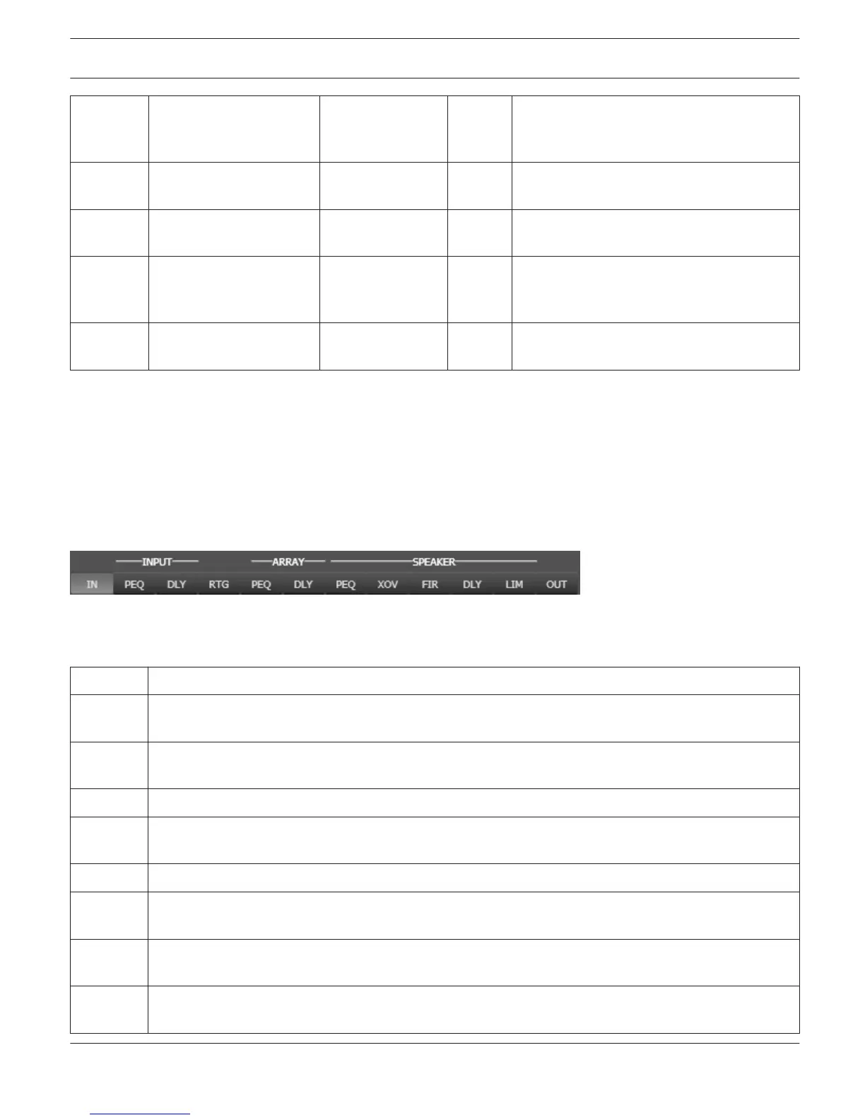
FLOW DIAGRAM SELECTOR
The Flow Diagram Selector can be accessed from any DSP page offering navigation icons within the DSP signal
processing functions. The Flow Diagram Selector lets you select different function blocks, where the currently selected
block is highlighted.
A short description of each DSP page is provided in the following table. Please refer to the corresponding chapters for
a more detailed explanation.
Page
Description
IN / RTG /
OUT
The signal flow display provides an overview of an amplifier’s DSP settings. This area also includes all
controls for the preset location and preset file management.
INPUT PEQ The Input Parametric EQ page provides access to the two 10-band parametric equalizers of the amplifier
inputs.
INPUT DLY This page allows the programming of delay lines for the amplifier channels A and B.
ARRAY
PEQ
The Array Parametric EQ page offers access to the 5-band parametric equalizers of the amplifier outputs.
ARRAY DLY This page allows the programming of delay lines for the output channels.
SPEAKER
PEQ
The Output Parametric EQ page offers access to the two 6-band parametric equalizers of the amplifier
outputs for speaker equalization.
SPEAKER
XOV
Frequency crossover-filters as well as the parameters trim, polarity and delay for both channels are
located in the Output X-Over area.
SPEAKER
FIR
This page provides a FIR-Filter for each amplifier channel.
IRIS-Net REMOTE AMPLIFIER | en 257
Bosch Security Systems B.V. User Manual 2017.05 | 3.20 | F.01U.119.956