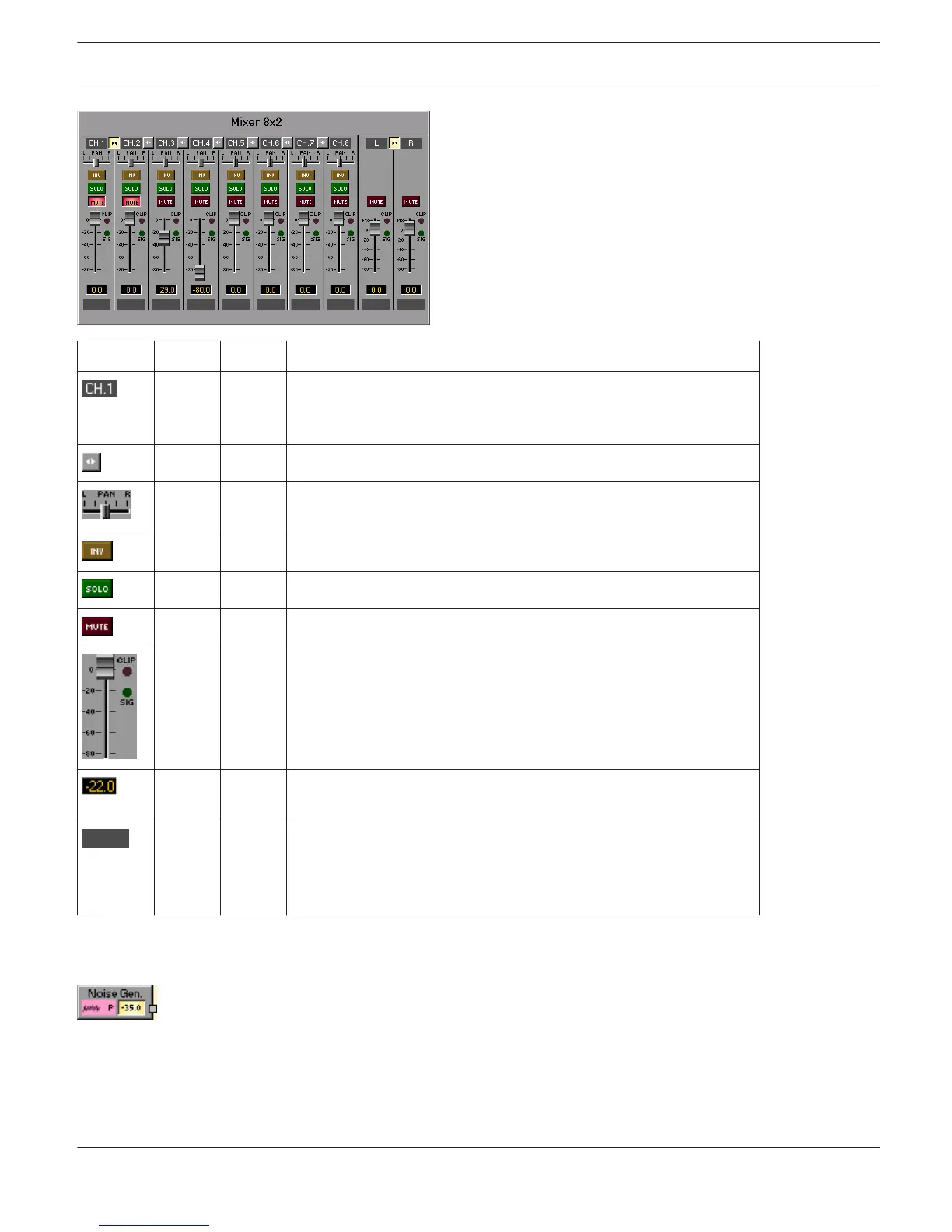
Element Default Range Description
Fixed channel naming: input channels are numbered from CH.1 to
CH.n. Output channel(s) are labeled OUT (Mono-Mixer) or L and R
(Stereo-Mixer).
LINK button for connecting (grouping) neighboring input channels.
Stereo Balance (Stereo-Mixer only) defines the percentage of the
input signal being distributed to the left or the right.
INV button for inverting the input channel.
SOLO button for monitoring a single input signal.
MUTE button for muting the corresponding input signal.
0.0 dB -80... 0
dB
Fader for setting the levels in corresponding inputs or outputs. If a
signal is present at the channel (above -40dBu), the "SIG" LED lights.
The "CLIP" LED additionally lights when the signal level nears
clipping (+21dBu).
The Fader Display indicates the current fader setting as a numerical
value and allows entering the desired value.
Text field for labeling an input channel with an internal IRIS-Net
name.
CAUTION: The use of * (asterisk) and = (equal) in names is not
permissible.
NOISE GENERATOR
The DSP block Noise Generator generates white or pink noise. Pink noise has a spectral dispersion with
constant power per relative bandwidth, whereas the octave from 20 to 40 Hz has the identical noise power as the
octave between 10000 and 20000 Hz. Every time the frequency is doubled the power is cut in half.
White noise has a spectral dispersion with constant power per absolute bandwidth, stated in Hz. The 20 Hz range
between 20 and 40 Hz has the same noise power as the 20 Hz range between 10000 Hz and 10020 Hz.
IRIS-Net DIGITAL MATRIX | en 440
Bosch Security Systems B.V. User Manual 2017.05 | 3.20 | F.01U.119.956