3-67
Confidential
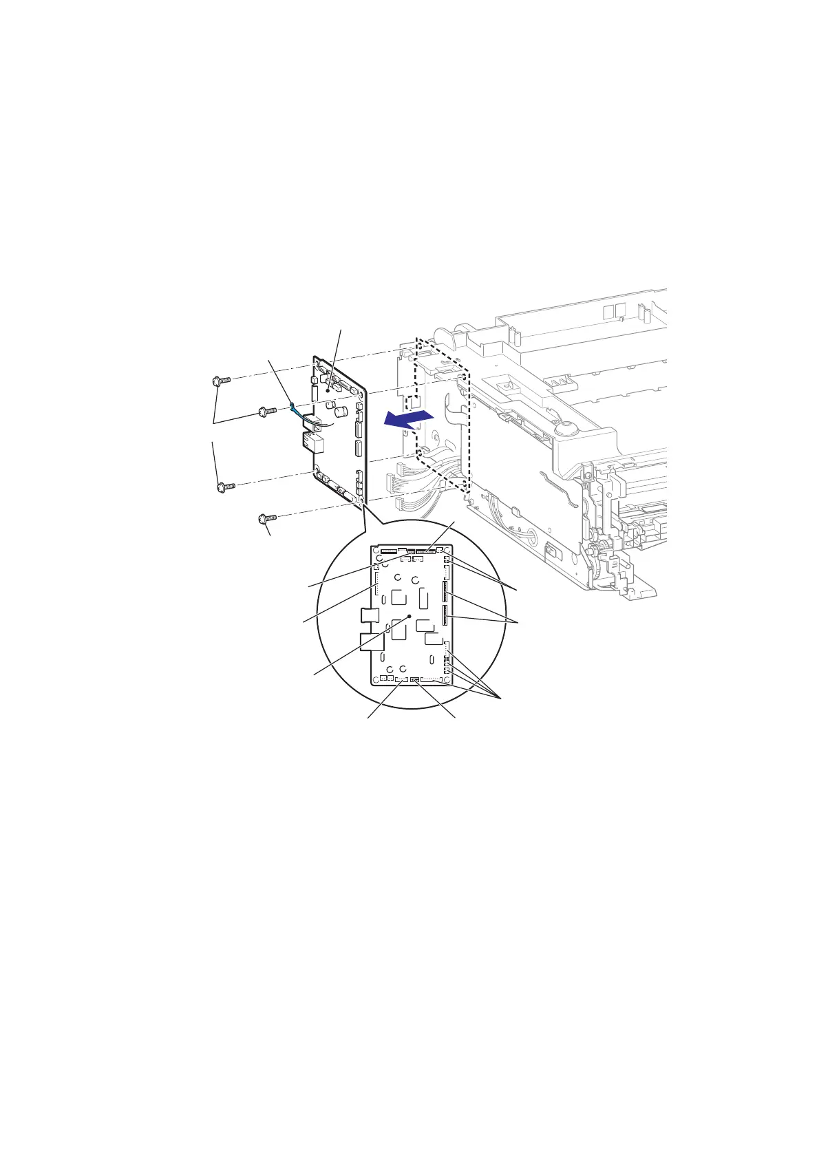
8.22 MAIN PCB ASSY
(1) Disconnect the five FFCs and the eight Connectors from the Main PCB ASSY.
(2) Remove the four Taptite cup S M3x6 SR screws, and then remove the FG harness
ASSY and the Main PCB ASSY from the Main body.
Fig. 3-66
Note:
• After disconnecting the flat cable(s), check that each cable is not damaged at its end or
short-circuited.
• When connecting the flat cable(s), do not insert it at an angle. After insertion, check that
the cable is not at an angle.
Assembling Note:
• If the FG harness ASSY which comes from the Laser unit is not connected, the Laser unit
may break down or not function correctly.
Replacement Main PCB Note:
When replace the main PCB, the function of the I FAX disappears.
Contact the customer to download the I FAX again.
FG harness ASSY
Taptite cup S M3x6 SR
FFC
FFC
FFC
FFC
Connector
Connector
Connector
Connector
Taptite cup S M3x6 SR
Main PCB ASSY
Main PCB ASSY
<Left side>
 Loading...