342
TRIM AND TILT
TROUBLESHOOTING
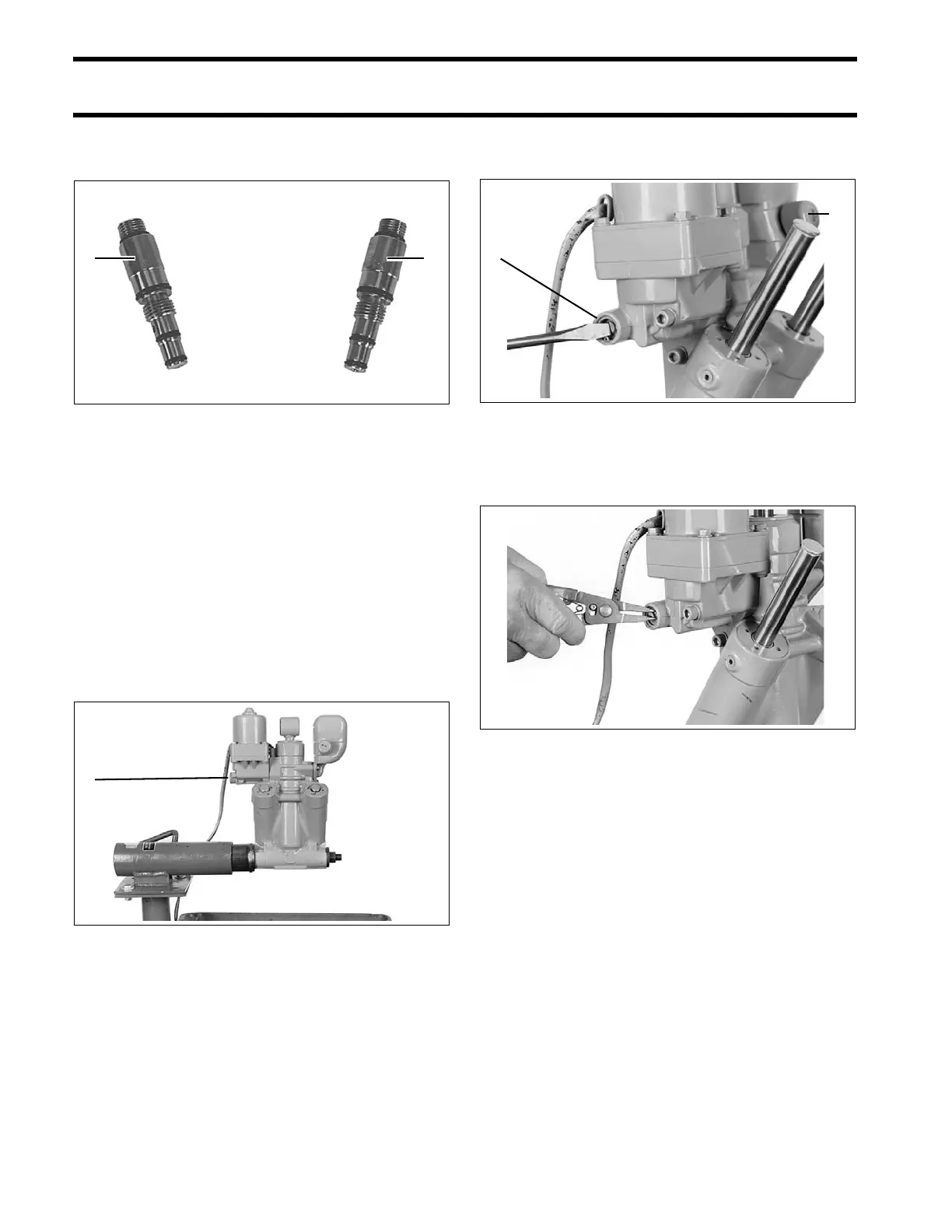
• The “B” adapter, P/N 336659, checks operation
of the DOWN circuit.
This kit do es no t includ e a gau ge and collar
assembly. Gauge and collar assembly shipp ed
with Power T rim/Tilt Service Kit, P/N 390 010, will
work. Gauge and Collar Assembly, P/N 983975, is
also available.
Be sure to use a fully charged battery.
STEP 1
Screw the man ual rele ase valve in the hyd raulic
unit unt il it is seate d. Place a la rge drain p an
under the unit to catch hydraulic fluid.
Operate the unit to the full UP po sition, the n run
the unit down momentarily to reduce pre ssure.
Loosen the reservoir cap one full turn. Loosen the
manual release valve three turns. Some fluid will
bypass the reservoir cap. These steps will relieve
the pressure in the unit.
Remove the manu al release valve ret aining ring
using retaining ring pliers.
Remove the manual release valve. Inst all pres-
sure gauge and adapter “A” to check pr oblems in
the UP circuit.
IMPORTANT: Torque gauge and ad apter lightly
to 5 to 10 in. lbs. (0.6 to 1.2 N·m). Excessive
torque might damage adapter or O-rings.
Cycle the unit down and up several times to purge
air. With all rods fully extended, run the unit down
momentarily to reduce pressure. Che ck fluid level
again, and add flu id if necessary. Remember that
1. A Adapter
2. B Adapter
27340
1. Manual release valve 41736
1. Manual release valve
2. Reservoir cap
41739
41754