343
TRIM AND TILT
TROUBLESHOOTING
14
all rods mu st be complete ly e xtended to check
fluid level.
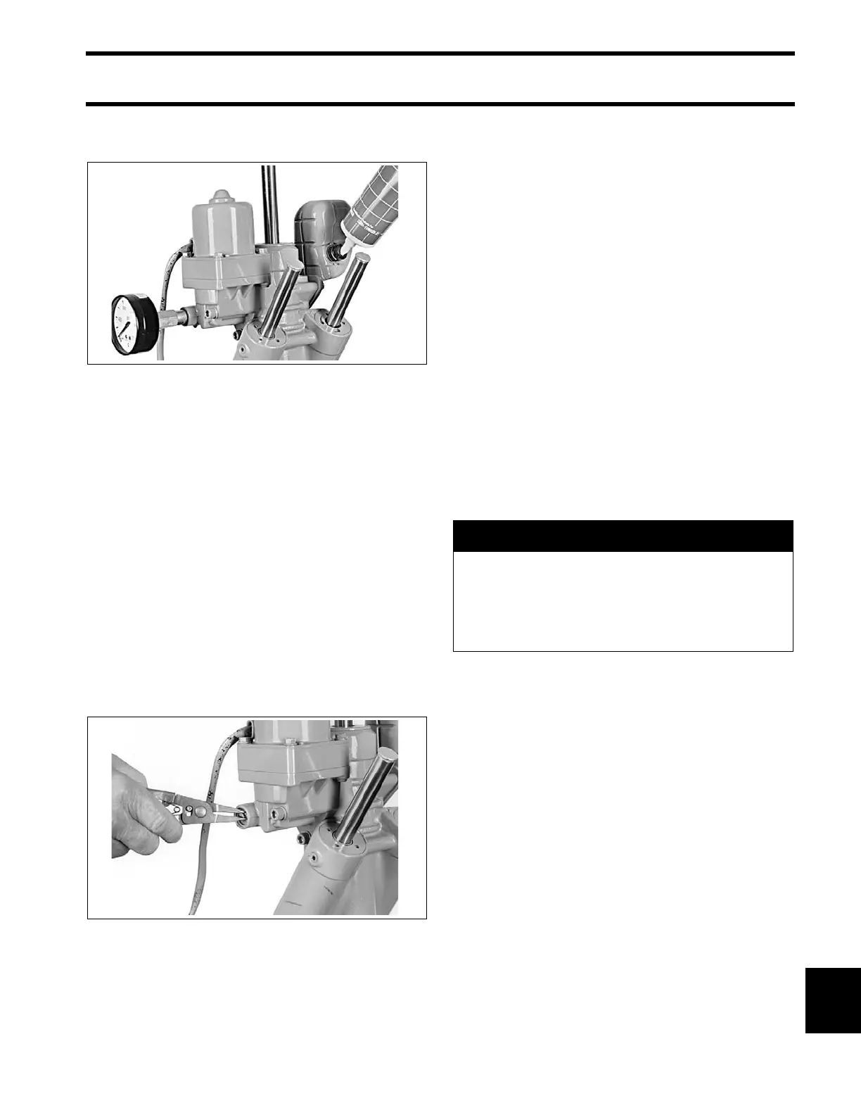
Starting with the tilt cylinder fully retracted, run the
unit UP.
• The gauge should show 0 to 200 psi (0 to 1379
kPa) as the tilt cylinder is extending.
• The gauge should show 1400 to 1600 psi (9653
to 11032 kPa) as the unit stalls.
• Release the switch and watch for a p ressure
drop. The stall pressure reading must not drop
more than 200 psi (1379 kPa) after motor stops.
If result s vary fro m the ab ove limit s, there is a
problem in the UP circuit. Refer to MODES OF
OPERATION on p. 334 for circuit description.
STEP 2
Remove th e man ual release valve ret aining ring
using retaining ring pliers.
Remove the manual release valve. Inst all pres-
sure gauge and adapter “B” to check pr oblems in
the DOWN circuit. Cycle the unit down and up
several times to p urge a ir. With all ro ds f ully
extended, run the un it down mome ntarily to
reduce pressure. Check fluid level again, and add
fluid if necessary. Remember that all rods must be
completely extended to check fluid level.
Starting with the tilt cylinder fully extended, run the
unit DOWN.
• The gauge should show 0 to 200 psi (0 to 1379
kPa) as the tilt cylinder is retracting.
• The gauge should sh ow approximately 800 p si
(5516 kPa) as the unit stalls.
• Release th e switch and watch for a pre ssure
drop. The stall pressure reading must not drop
more than 200 psi (1379 kPa) after motor stops.
If result s vary from the abo ve limit s, there is a
problem in the DOWN cir cuit. Refer to MODES
OF OPERATION on p. 334 for circuit description.
Check fluid level again and add fluid, if necessary.
41757
41754
A CAUTION
After tes ts are c omplete, run the unit up,
then down moment arily. Cycle the unit
down and up seve ral times to purge air .
With all rods fully e xtended, ru n the unit
down momentarily to reduce pressure.