214
POWERHEAD
POWERHEAD ASSEMBLY
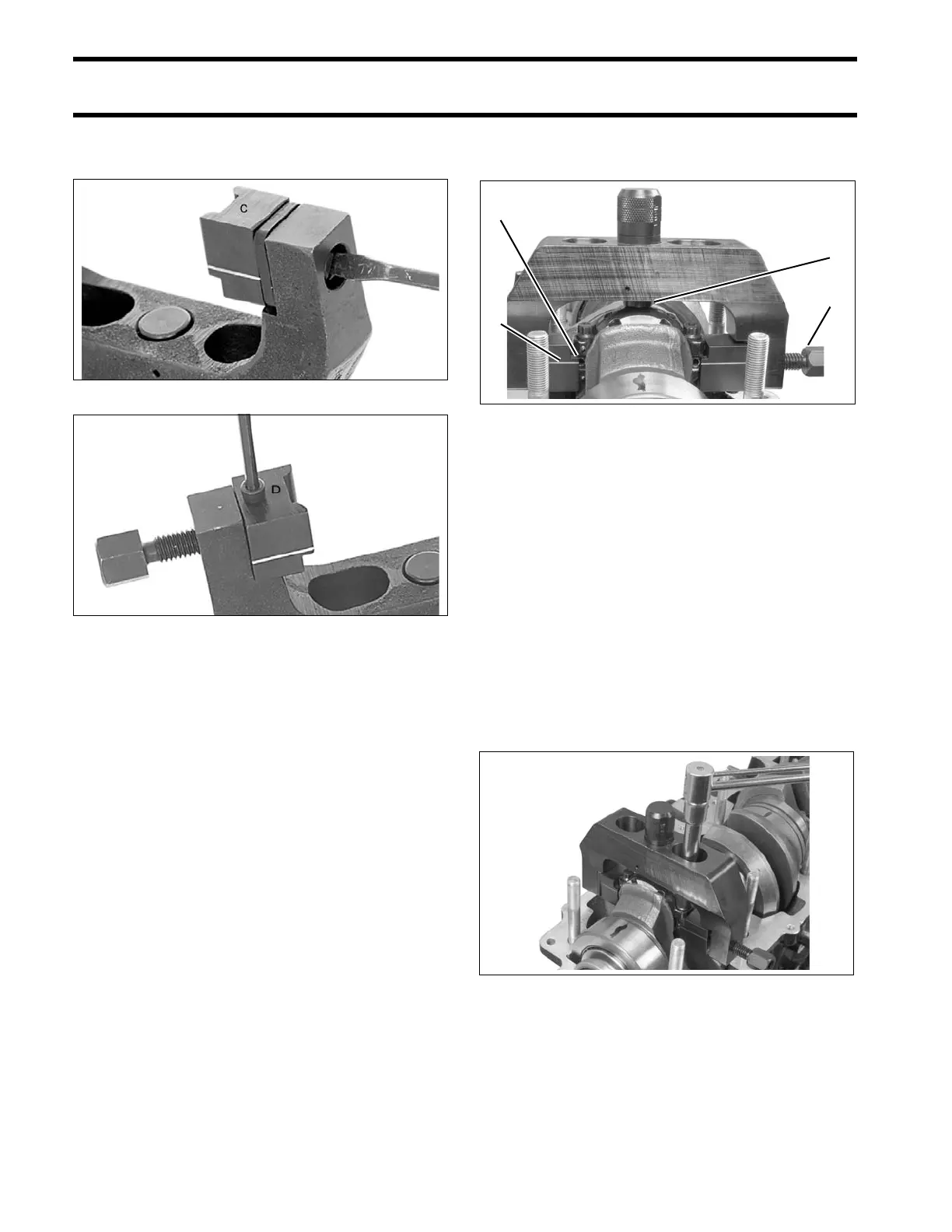
Secure restraining jaw “C” and forcing jaw “D” to
frame.
Apply a light coat of outboard lubricant to the cor-
ners of the connecting rod and rod cap. Place
frame on connecting rod using the following pro-
cedure.
• Place frame onto the connecting rod so the con-
tact area of the jaw is centered on the side of
the rod.
• Tighten forcing screw until jaws contact con-
necting rod.
• Slide frame down until adjustment stop contacts
the rod cap. The groove lines on the jaws must
be centered on the rod/crankpin diameter.
• Tighten the forcing screw to a torque of 14 to 16
in. lbs. (1.6 to 1.8 N·m).
IMPORTANT: Make sure that frame is squarely
in position and that rod and cap are aligned.
Loosen both rod cap screws one-quarter turn.
Use Torquing Socket, P/N 331638, to tighten rod
cap screws in three stages:
• Apply first torque of 40 to 60 in. lbs. (5 to 7 N·m)
to both rod cap screws.
• Tighten screws to a torque of 14 to 16 ft. lbs. (19
to 21.7 N·m).
• Apply final torque of 30 to 32 ft. lbs. (41 to 43
N·m).
IMPORTANT: If a new screw is used, it must be
installed as above. Then, it must be removed, re-
lubricated, and installed again.
Loosen forcing screw and remove the frame.
Restraining Jaw “C” 21591
Forcing Jaw “D” 21594
1. Contact area of jaw
2. Forcing screw
3. Adjustment stop
4. Groove line
002071
002072