92
Z31900_00_01
Maintenance
10.4 Lift Adjustment
i
Not all connections may be available depending on the configuration.
1. Check the pressure gauge (Figure 10.1/6).
2. If the pressure is below 4 bar, turn the adjustment (Figure 10.1/5) clockwise until the
pressure gauge displays 4 bar.
The speed of the sample transported out of the magnet can be varied by regulating the
outlet air flows of the cylinder supply connections. A small needle valve is fitted on the
exhaust outlet. The needle valves can be manually set to change the linear speed.
NOTICE
Material damage hazard from heavy samples!
Samples may be damaged due to incorrect sample lift pressure adjustment.
f Adjustment is valid only for 1 sample configuration and weight.
f Personal must be trained.
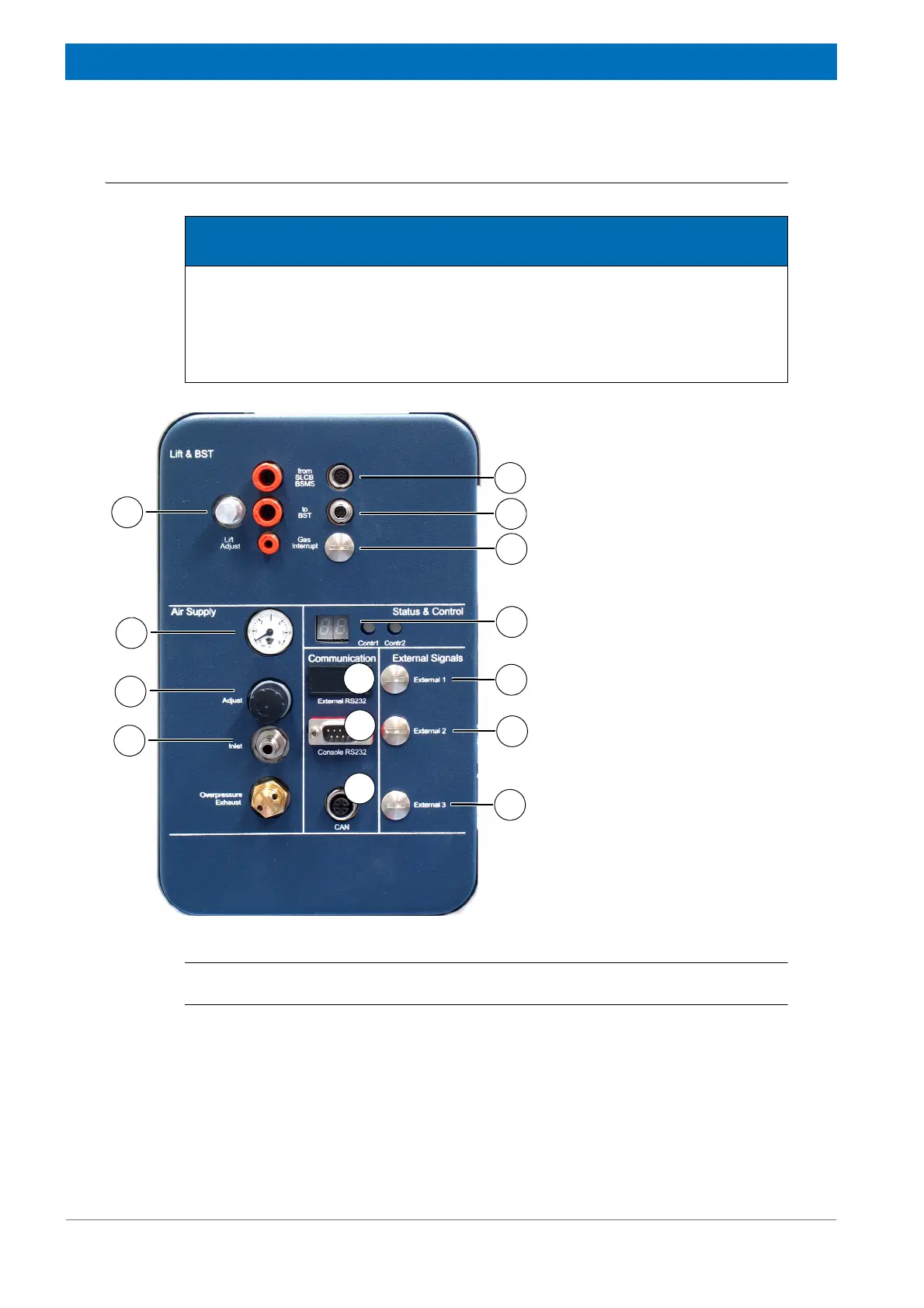
Figure 10.1 Connections Left Side
1. BST Interface Cable from
SLCB BSMS
2. BST Interface Cable to BST
3. Gas Interrupt (future feature)
4. Lift Adjustment Knob
5. Status and Control
6. Pressure Gauge
7. Air Supply Adjustment Knob
8. Air Supply
9. External R232 (future feature)
10. Console RS232
11. CAN Network to Control
Panel
12. External Signal 1 (future fea-
ture)
13. External Signal 2 (future fea-
ture)
14. External Signal 3 (future fea-
ture)
1
2
3
4
6
5
7
8
9
10
11
12
13
14