A-15
Scanner
®
2000 microEFM Appendix A
SWITCH
J1
TB1
BATTERY
13
14
J2
SCANNER 2000
Main Circuit Board
PN: 9A-30160010
TFM 1 RTD
I
+
R
+
R
-
I
-–
+
2
3
4
5
6
1
POWER
PORT 2
PORT 1
–
+
–
+
–
+
7
8
9
10
11
12
TB2
TB3
DIG OUT 1
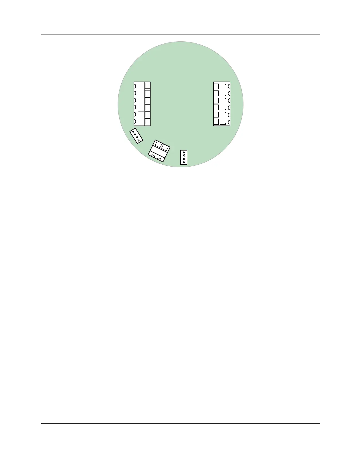
Figure A.19—J2 receptacle for installing the seal kit jumper
5. Complete eld wiring, if applicable, while the circuit board is exposed.
6. Reposition the switchplate and circuit board assembly against the standoffs and secure by replacing one
of the switchplate screws that was removed in step 3. Do not replace the opposite screw; the seal kit screw
and bracket will be installed in its place.
7. Install the wire seal as follows:
a. Position the S-shaped metal bracket from the kit over the edge of the switchplate so that the screw
hole in the bracket aligns with the screw hole in the switchplate (see Figure A.20, page A-16). When posi-
tioned correctly, the portion of the bracket that contains a tiny drill hole will be nearest the display.
b. Place the Allen head screw through the bracket and the switchplate and gently tighten with the Allen
wrench provided to secure the switchplate assembly in the enclosure. Adjust the screw as required to
align the drilled hole in the screw with the hole in the bracket.
c. Insert the free end of the seal wire through the Allen head screw and through the hole in the metal
bracket (see Figure A.20, page A-16).
d. Thread the seal wire through the holes in the lead seal to form a loop. Pull the excess wire through the
seal until the loop around the seal is approximately 1/2 in. in diameter and the seal is near the metal
bracket (see Figure A.21, page A-16). Do not overtighten the seal wire; doing so will make the seal dif-
cult to remove later.
e. Crimp the lead seal rmly to lock the seal wire in place and remove the excess wire.
8. Replace the cover on the enclosure.
9. Verify that the conguration settings in ModWorX Pro are accurate.
10. Enable the custody transfer device seal in the ModWorX Pro interface as described in the ModWorX Pro
User Manual, Part No. 9A-30165025.