80
Section 5 Scanner
®
2000 microEFM
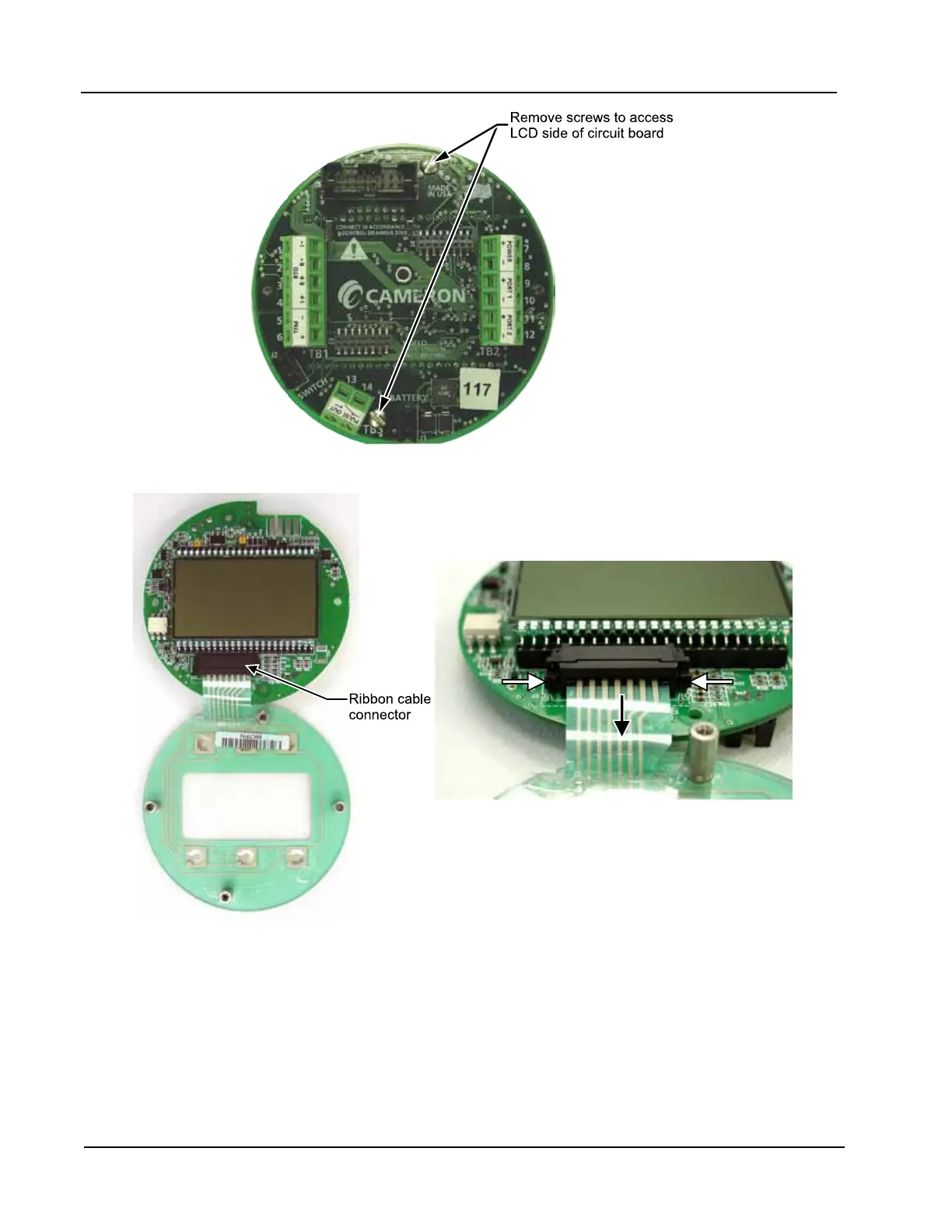
Figure 5.3—Disassembly of circuit board/keypad assembly
13. Connect the circuit board to the keypad with the two #4-40 × 5/16” screws removed in step 9.
14. Reconnect the sensor ribbon cable to the J5 connector at the top of the circuit board, by inserting the rib-
bon cable into the black clip and securing the latch on the clip to hold it tightly in place.
15. Reconnect the battery cable to connector J1 on the circuit board.
16. Reconnect all wiring to terminal blocks TB1, TB2 and TB3 (and J2, if applicable).
17. Reattach the display/keypad assembly to the standoffs inside the enclosure with the two #4-40 × 7/8”
screws removed in step 2.
Figure 5.4—To release the ribbon cable from the
connector, press in on the side tabs of the J7 connector
(white arrows) and gently pull forward (black arrow).