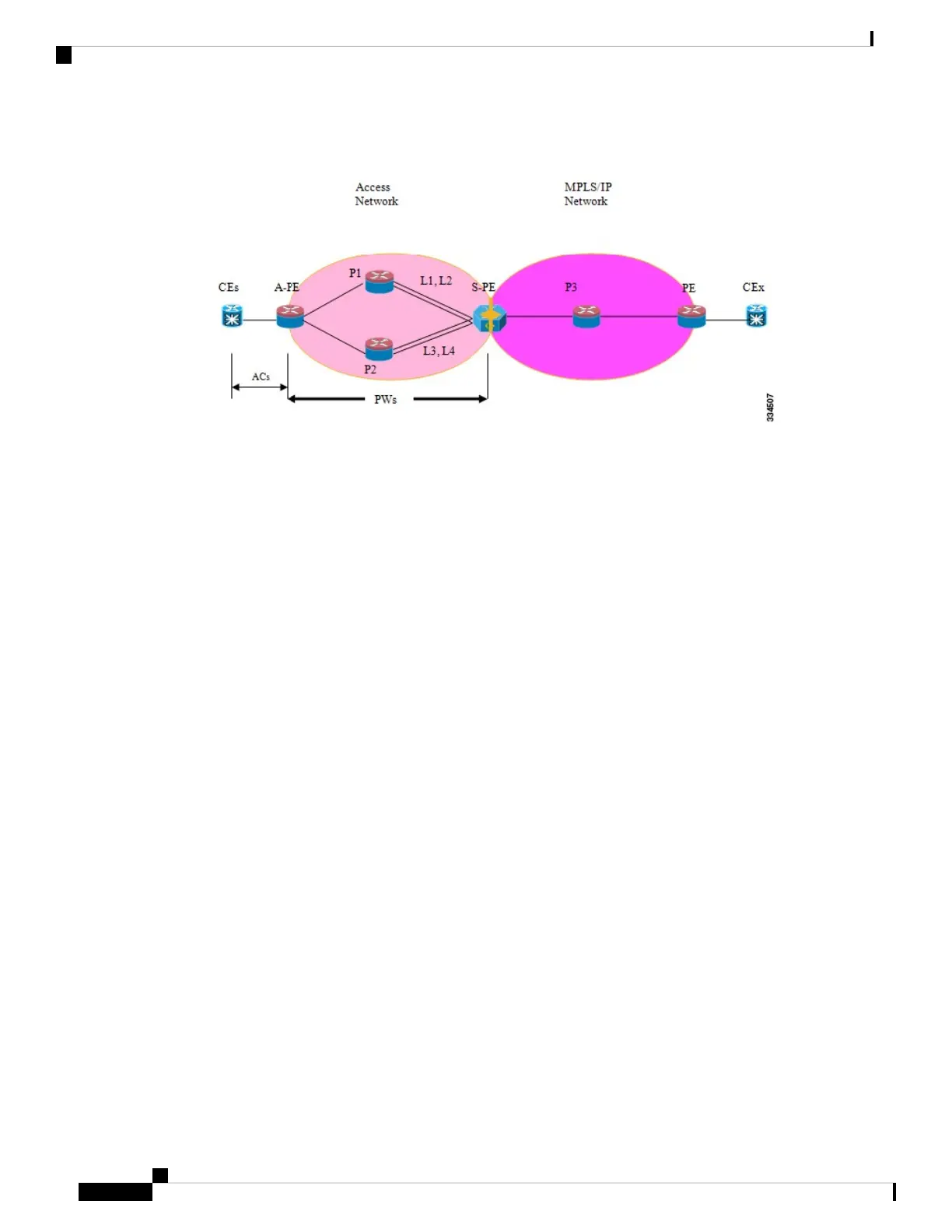
Figure 39: Pseudowire Headend Example
There are multiple CEs connected to A-PE (each CE is connected by one link). There are two P routers between
A-PE an S-PE in the access network. The S-PE is connected using two links to P1. These links L1 and L2
(on two different line cards on P1 and S-PE), e.g. Gig0/1/0/0 and Gig0/2/0/0 respectively.
The S-PE is connected by two links to P2, links L3 and L4 (on two different line cards on P2 and S-PE), e.g.
Gig0/1/0/1 and Gig0/2/0/1 respectively. For each CE-APE link, a xconnect (AC-PW) is configured on the
A-PE. A-PE uses router-id 100.100.100.100 for routing and PW signaling. Two router-ids on S-PE used for
PW signaling, e.g. 111.111.111.111 and 112.112.112.112 (for rx pin-down), 110.110.110.110 is the router-id
for routing.
CE Configuration
Consider two CEs that are connected through Ge0/3/0/0 (CE1 and A-PE) and Ge0/3/0/1 (CE2 and A-PE).
CE1
interface Gig0/3/0/0
ipv4 address 10.1.1.1/24
router static
address-family ipv4 unicast
110.110.110.110 Gig0/3/0/0
A.B.C.D/N 110.110.110.110
CE2
interface Gig0/3/0/1
ipv4 address 10.1.2.1/24
router static
address-family ipv4 unicast
110.110.110.110 Gig0/3/0/1
A.B.C.D/N 110.110.110.110
A-PE Configuration
At A-PE we have 1 xconnect for each CE connection. Here we give the configuration for the 2 CE connections
above: both connections are L2 links which are in xconnects. Each xconnect has a PW destined to S-PE but
we use a different neighbor address depending of where we want to pin-down the PW: [L1, L4] or [L2, L3]
L2VPN and Ethernet Services Configuration Guide for Cisco ASR 9000 Series Routers, IOS XR Release 6.3.x
348
Implementing Multipoint Layer 2 Services
Configuring Pseudowire Headend: Example
 Loading...


