Figure 4: L2PT in forward mode
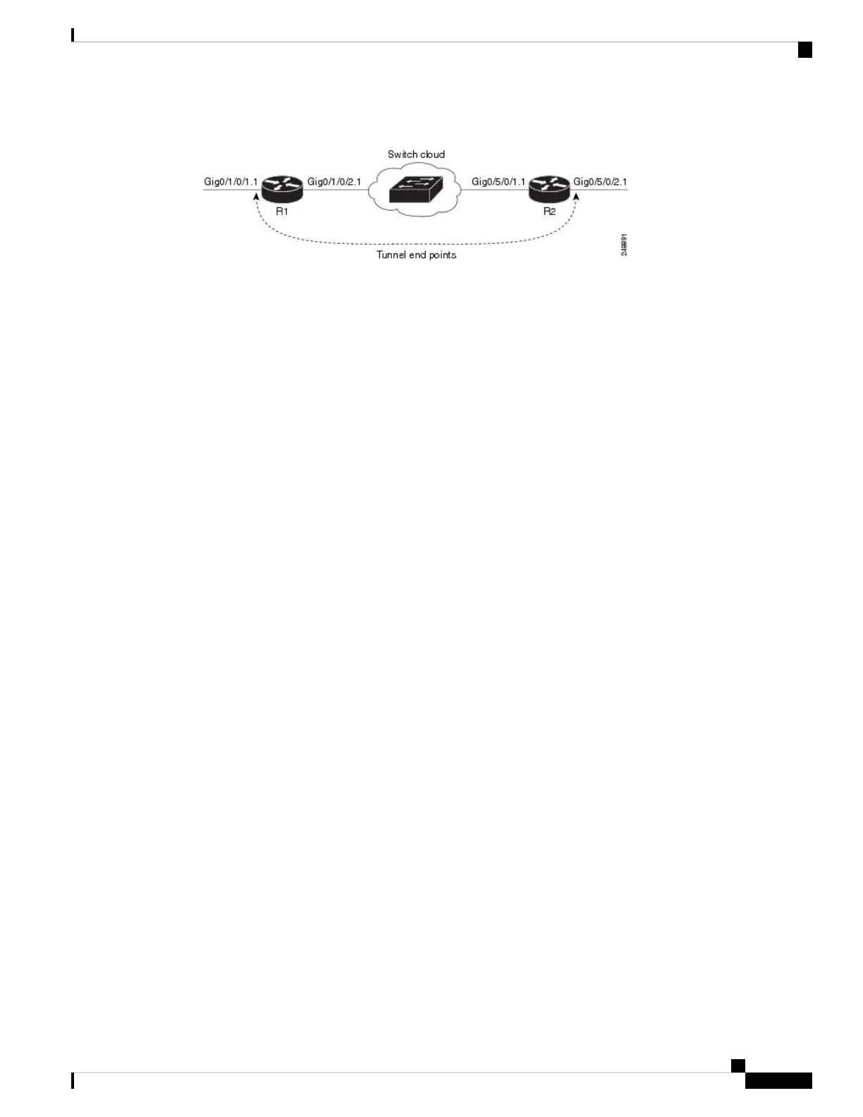
A Service Provider network (S-network) is depicted in Figure 1. The customer network (C-network) connects
to router R1 at the GigabitEthernet subinterface 0/1/0/1.1, and to router R2 at the GigabitEthernet subinterface
0/5/0/2.1. The C-network is not shown in the diagram; however, the C-network sends L2 traffic through the
S-network, and the S-network switches the traffic from end to end. The customer traffic also carries L2 protocol
frames. The purpose of L2PT is to allow these protocol frames to pass through the S-network. In forward
mode, L2PT is applied to the customer facing interfaces of the S-network, R1 GigabitEthernet 0/1/0/1.1 and
R2 GigabitEthernet 0/5/0/2.1.
Figure above depicts the configuration for L2PT in forward mode: :
R1:
!
interface GigabitEthernet0/1/0/1
negotiation auto
!
interface GigabitEthernet0/1/0/1.1 l2transport
encapsulation default
l2protocol cpsv tunnel
!
interface GigabitEthernet0/1/0/2
negotiation auto
!
interface GigabitEthernet0/1/0/2.1 l2transport
encapsulation default
!
l2vpn
xconnect group examples
p2p r1-connect
interface GigabitEthernet0/1/0/1.1
interface GigabitEthernet0/1/0/2.1
!
!
!
R2:
!
interface GigabitEthernet0/5/0/1
negotiation auto
!
interface GigabitEthernet0/5/0/1.1 l2transport
encapsulation default
!
interface GigabitEthernet0/5/0/2
negotiation auto
!
interface GigabitEthernet0/5/0/2.1 l2transport
encapsulation default
l2protocol cpsv tunnel
!
L2VPN and Ethernet Services Configuration Guide for Cisco ASR 9000 Series Routers, IOS XR Release 6.3.x
41
Ethernet Features
L2PT in the Forward Mode
 Loading...


