Chapter 3 Disassembly and Maintenance
3-6. Disassembly, Reassembly and Lubrication
3-17 CL-E700 series
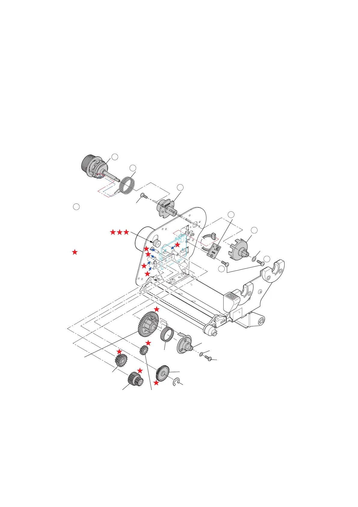
3-6-5. “SA Ribbon Tension Unit R”, “SA Ribbon Encoder” and Ribbon
Gears
(1) “SA Ribbon Tension Unit R” and “SA Ribbon Encoder”
1. Remove the “SA2 Ribbon Unit Fan”. Refer to “3-6-3 “Unit Ribbon” Covers”.
2. Remove the 1 screw (No0 PH(4-0.3) M2x3 (NI)) (
) and detach the “Plate Ribbon
Washer” and the “Holder Ribbon Shaft Encoder” ().
3. Remove the “SA Ribbon Tension Unit R” () and the “Spring Ribbon Return R” ().
4. Remove the 2 screws (No0 PH(4-0.3) M2x3 (NI)) () and detach the “Holder Clutch
Shaft” ().
5. Remove the 1 screws (No0 PH(4-0.3) M2x3 (NI)) (), disconnect the connector J605,
and detach the “SA Ribbon Encoder” ().
Note on reassembling:
• Correctly hook both ends of the “Spring Ribbon Return R” () on the hook part of the
“SA Ribbon Tension Unit R” () and “Holder Clutch Shaft” ().
To correctly hook them, refer to “
3-5-3 SA Ribbon Tension Unit R”.
After h
ooking both
ends, rotate the “SA Ribbon Tension Unit R” () right and left to be sure that it returns to
the original position by the spring force.
: FLOIL G-474C
1
2
3
4
6
J605
Holder Ribbon
Shaft Encoder
Holder Clutch Shaft
Spring Ribbon Return R
No0 PH(4-0.3) M2x3 (NI)
SA Ribbon Tension Unit R
Plate Ribbon Washer
No0 PH(4-0.3)
M2x3 (NI)
SA Ribbon Encoder
No0 PH (4-0.3) M2x5(NI)
Plate Ribbon Washer
SA Holder R Shaft
Spring
Ribbon Return
Gear 2 Ribbon
E-Ring 4.0
Gear 3 Ribbon
Gear Reduction Ribbon 1
Gear 5F Ribbon
5
7
8
Gear 4 Ribbon

 Loading...


