Chapter 2 Operating Principles
2-2. Operation of Control Parts
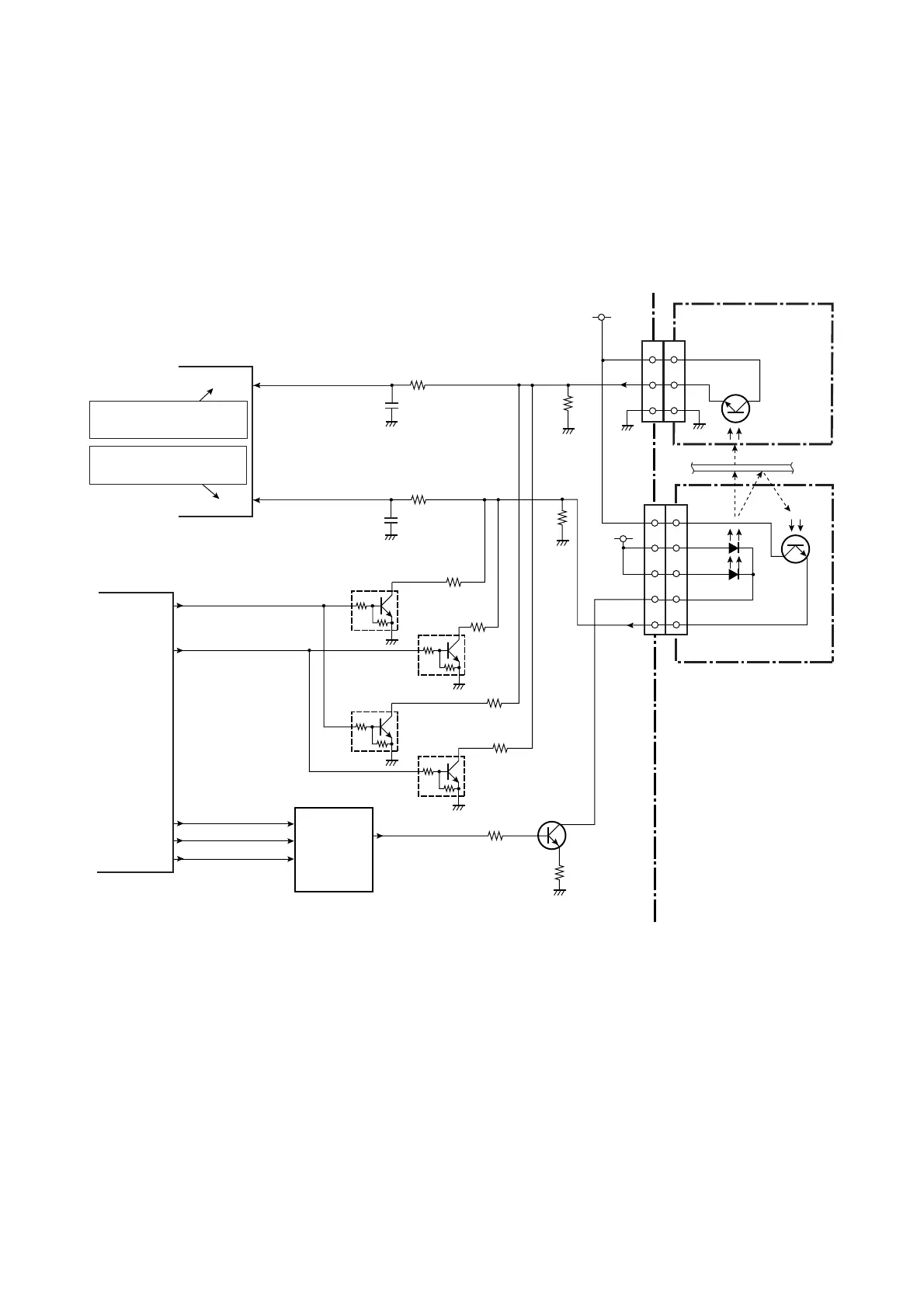
CL-E700 series 2-24
(2) Transparent sensor (SA TRA Sen PCB) and reflective sensor (SA Ref Sensor
PCB)
The transparent sensor and the reflective sensor are used together to detect labels stuck on
the liner or U-shaped notches on tag. On the other hand, the reflective sensor alone is used to
detect black marks printed on the bottom surface of tag. Both sensors are also used to detect
the media end.
The upper side transparent sensor is the phototransistor, and the lower side reflective sensor
consists of 2 LEDs and 1 phototransistor. Media passes between these sensors.
Transparent sensor and reflective sensor (for detecting labels or U-shaped notches):
When the portion of the liner where no label stuck on it passes between both sensors, the light
emitted from the reflective sensor’s LEDs reaches the transparent sensor, passing through the
liner only. Thus, the transparent sensor (phototransistor) conducts and the voltage
corresponding to the amount of light is applied to pin 96 (SNSTRA) of the CPU (U1A).
Meanwhile, when the portion of the liner where the label stuck on it passes between both
sensors, the light is blocked by the label and the transparent sensor (phototransistor) turns
OFF. Thus, pin 96 (SNSTRA) of the CPU goes to “Low” level. From these levels, the CPU can
detect the arrival of the label leading edge. When media runs out, since the light emitted from
the LEDs directly falls on the transparent sensor continuously, media end can be detected. In
this case, pin 96 (SNSTRA) of the CPU will go to “High” level.
R103
C132
R98
C130
R99
R93
Q8
DTC114EM
Q9
DTC114EM
R94
R92
Q7
2SC5658
+5V
Media
Transparent Sensor
Reflective Sensor
3
2
3
4
1
4
5
J9
2
1
[SA TRA Sen PCB]
[SA Ref Sensor PCB]
U16
LD
CLK
13
12
DI
11
DASENS
DACDAT
DACCD
DACSCK
R2A20164SA
Transparent sensor
output sensing terminal
J8
+3.3V
SNSREF
SNSTRA
AN2
96
AN1
95
CPU
Reflective sensor output
sensing terminal
R97
R96
N11
N9
SNSCTL1
SNSCTL0
AO1
AO2
3
44_N11
44_N9
FPGA
R102
R101
Q10
DTC114EM
Q11
DTC114EM
[SA Main PCB]
U1A
U5
D/A Converter
B5
82_B5
B4
82_B4
D4
14_D4
3
2
1
CN401
3
4
1
5
2
CN501

 Loading...


