Chapter 2 Operating Principles
2-2. Operation of Control Parts
CL-E700 series 2-18
2-2. Operation of Control Parts
2-2-1. Configuration of Printer
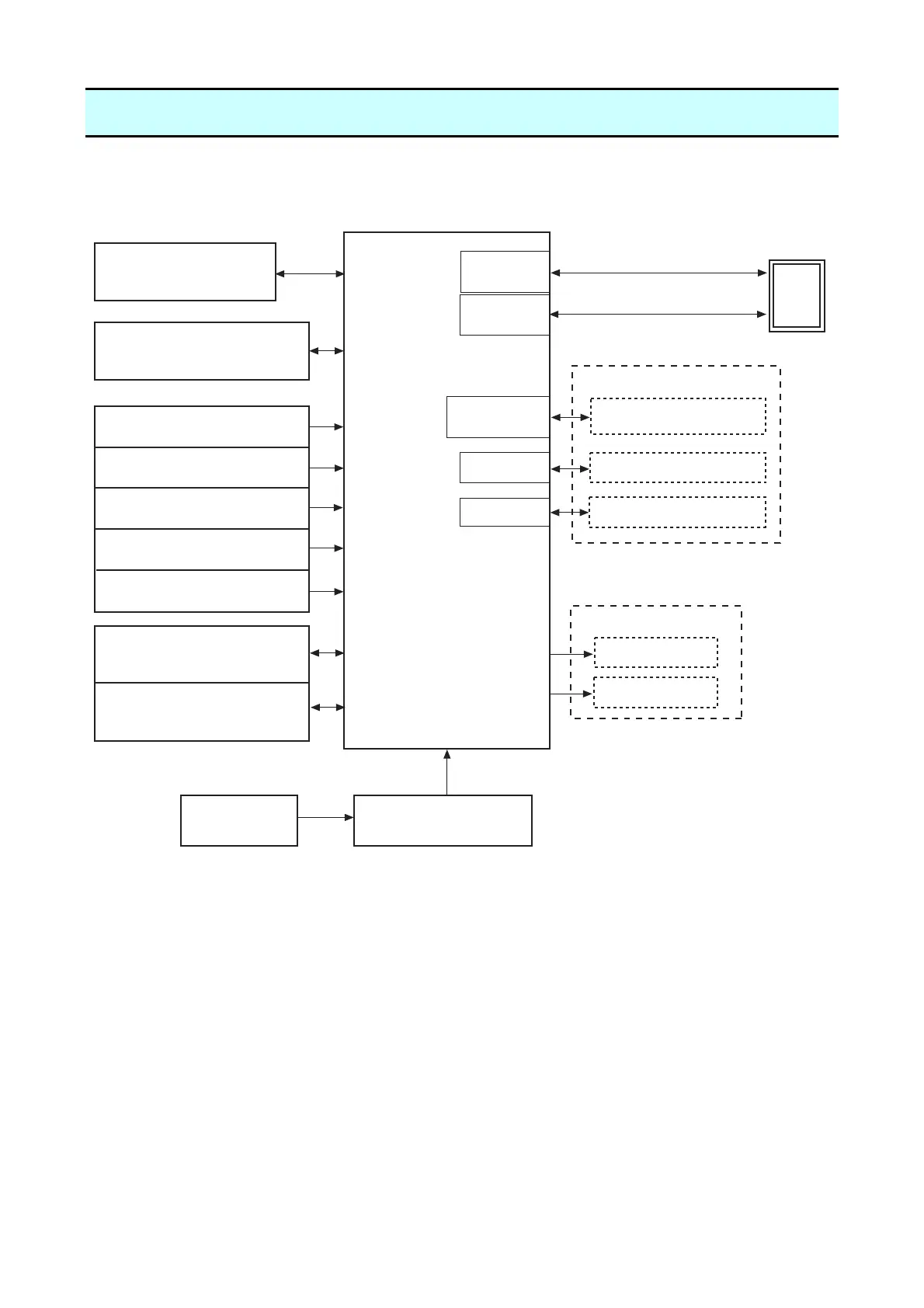
The following shows major configuration blocks.
Major functions of individual components are described below:
(1) Filter & power supply section
Consists of a fuse, a filter circuit to eliminate external electric noise, and a switching type
regulator to transform an AC input to +24V DC output.
(2) SA Main PCB
Controls the entire operations of the printer. It consists of CPU, ROM, RAM, FPGA, driver
circuits, etc.
(3) Operation panel (SA Opepane PCB)
A panel used to indicate the operating status of the printer and to set specifications. It consists
of 4 keys, 1 LED (Green/Red) and 1 LCD.
Head Up Sensor
[SA Head Up Sensor PCB]
Transparent Sensor
[SA TRA Sen PCB]
Reflective Sensor
Ref Sensor PCB]
Filter & Power Supply
[Unit Power Supply]
AC Inlet &
Power Switch
Serial I/F
(USB)
Serial I/F (RS-232C)
Host
(PC)
PF Motor
[SA PF Motor]
(PF Motor Temp. Sensor)
Thermal Head
[SA Head]
(Head Temp. Sensor)
Operation Panel
[SA Opepane PCB]
[SA Main PCB]
Parallel I/F
Ribbon Motor
[SA Ribbon Motor F]
(Ribbon Motor Temp. Sensor)
Ribbon Tension Sensor
[SA Ribbon Sensor]
Cutter
Peeler
Parallel I/F
LAN I/F
(Options)
(Options)
+24V
Wi-Fi I/F
Serial I/F
Wi-Fi I/F
Ribbon Encoder Sensor
[SA Ribbon Encoder]
[SA

 Loading...


