Chapter 3 Disassembly and Maintenance
3-6. Disassembly, Reassembly and Lubrication
CL-E700 series 3-34
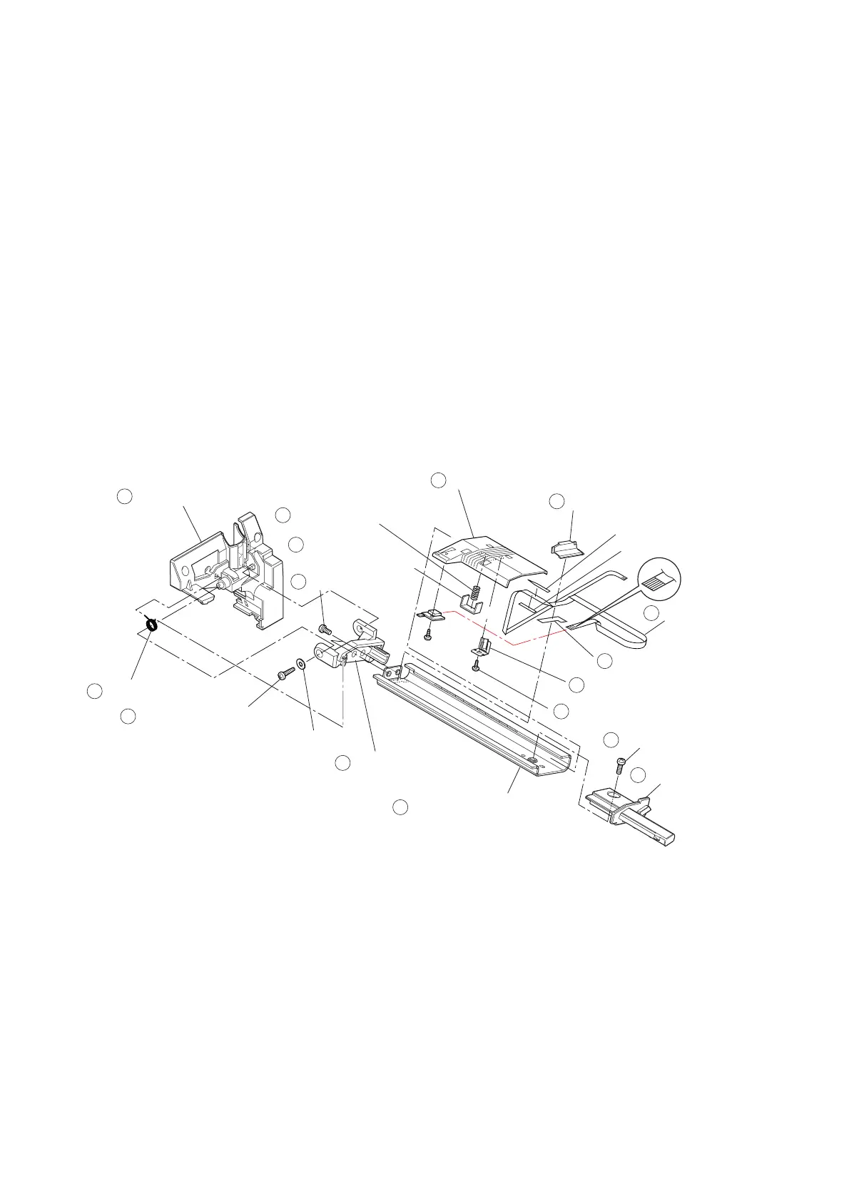
(3) “FFC TRA Sensor” and “Leaf Adjust Sensor U”
1. Remove the 1 screw (NO1 PHT
M2.0x8 (NI)) () and 1 plain washer (2x5x0.3 (NI)),
and detach the “Unit Sensor U” Block from the “Cover Head Wire” (). At this time,
also remove the “Spring Sensor Frame” ().
2. Remove the 1 screw (BH M3.0x6 (NI)) () and detach the “Cap Sensor Frame R” ()
to the right.
3. Remove the “Cap Sensor Cable U” () to set the “FFC TRA Sensor” () free.
4. Remove the 2 screws (PH M2.6x3 (NI)) () and detach the “Cap Sensor Frame L”
().
5. Slide the “Holder Sensor U” () to the right and detach the “FFC TRA Sensor” ().
6. Peel off the “Sheet Cable Support A” and “Sheet Cable Support B” from the “FFC TRA
Sensor” ().
7. Remove the “Plate Friction Sen U” () and “Spring Friction Sen U” () from the
“Holder Sensor U” ().
8. Remove the 1 screw (NO.0 TFH (PT4-0.5) M2.0x4) () and detach the “Leaf Adjust
Sensor U” () from the “Holder Sensor U” ().
9. Peel off the “Tape Sensor Cable U” () from the “Plate Sensor Holder U” ().
Cover Head Wire
Spring Sensor Frame
NO1 PHT M2.0x8 (NI)
2x5x0.3 (NI)
PH M2.6x3 (NI)
Holder Sensor U
Cap Sensor Cable U
FFC TRA Sensor
BH M3.0x6 (NI)
Cap Sensor Frame R
Plate Sensor Holder U
Leaf Adjust Sensor U
Sheet Cable Support A
Tape Sensor Cable U
Sheet Cable Support B
Spring Friction Sen U
NO.0 TFH (PT4-0.5) M2.0x4
1
2
3
4
5
6
7
Cap Sensor Frame L
8
9
10
13
14
15
11
16
Plate Friction Sen U
12

 Loading...


