Chapter 3 Disassembly and Maintenance
3-6. Disassembly, Reassembly and Lubrication
3-21 CL-E700 series
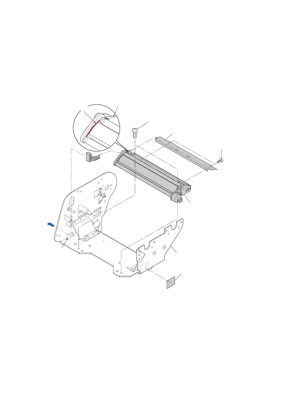
3-6-9. “SA Ribbon Tension Shaft F” and “SA Ribbon Sensor”
(1) “Ribbon Sensor Frame F” Block
1. Remove the “SA2 Ribbon Unit Fan”. Refer to “3-6-3 “Unit Ribbon” Covers”.
2. Remove the 2 screws (B
H M3.0x3 (NI)) and detach the “Ribbon Sensor Frame F” Block
from the “SA Ribbon Frame (with Support)”.
3. Remove the 2 screws (No0 PH(4-0.3) M2x3 (NI)) and detach the “Cover RBN Tension
Adjust”.
4. Peel off the “Label Ribbon Tension Adjust” from the “SA Ribbon Frame (with Support)”.
Notes on reassembling:
• Referring to the magnified view, mount the “Cover RBN Tension Adjust” so that the
spring end of the “Ribbon Sensor Frame F” Block is under the “Cover RBN Tension
Adjust”.
• Pass the connector J606 through the hole “A” in the frame.
• When remounting the “Ribbon Sensor Frame F” Block, perform the ribbon slant
elimination adjustment. Refer to “
3-7-2(1) Ribbon Left-Right Balance Adjustment Knob
(For user)”.
•
Once the label is peele
d off, it cannot be reused.
BH M3.0x3 (NI)
Cover RBN Tension Adjust
No0 PH(4-0.3) M2x3 (NI)
"Ribbon Sensor Frame F" Block
Spring end
J606
Spring
[Should be under the cover.]
A
SA Ribbon Frame (with Support)
Label Ribbon Tension Adjust

 Loading...


