Chapter 2 Operating Principles
2-2.
Operation of Control Parts
2-31 CL-E700 series
Holder Ribbon Shaft Encoder
[Right side view]
Ribbon
Photointerrupter
SA Ribbon Encoder
(Ribbon Encoder Sensor)
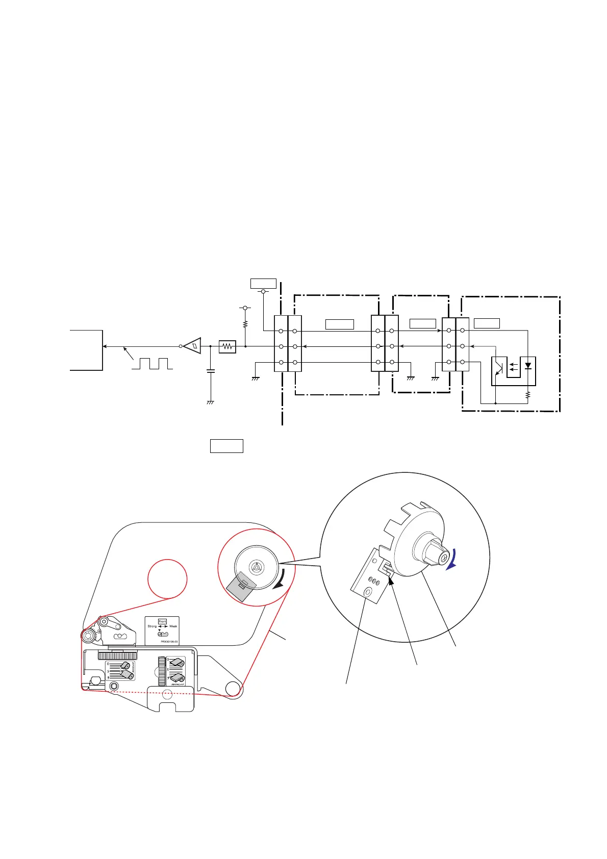
(7) Ribbon encoder sensor
The ribbon encoder sensor consists of one photointerrupter and is located on the ribbon supply
side (rear side) of the “Unit Ribbon”. It is used to detect the running status of ribbon as well as
the ribbon end.
While the ribbon is running, the “Holder Ribbon Shaft Encoder” (supply reel) is rotated by the
running ribbon and its slits on the bottom cross the interrupter (PS501) on the “SA Ribbon
Encoder”. Thus, a pulse train is output from the interrupter to pin 43 (RIBSENS_ENC) of the
CPU (U1A).
When the ribbon runs out during printing, the CPU detects the ribbon end state as no pulse
train is given. When the ribbon end is detected, the LED on the operation panel blinks in red
and the LCD displays “Error Ribbon End”, and the printer goes off-line.
* In power saving mode, +3VIO is not supplied. For details, refer to “2-2-6(1) Power supply
circuit”.
[SA Ribbon Encoder]
2
3
1
PT501
Ribbon Encoder Sensor
2
3
1
J605
[SA Ribbon
Control PCB]
12
J601
CPU
43
P6_12
12
PS501
R501
1
1
RIBENC
C106
RIBSENS_ENC
RA17
5
6
U12C
R79
[SA Main PCB]
14-16
14-16
J304
23
J301
23
8
8
RIB_SENS_ENC
3-6
J4
[SA Relay PCB]
U1A
3-6
+3.3V
+3VIO
+3VIO
+3VIO
+3VIO

 Loading...


