Chapter 3 Disassembly and Maintenance
3-7. Adjustments
CL-E700 series 3-60
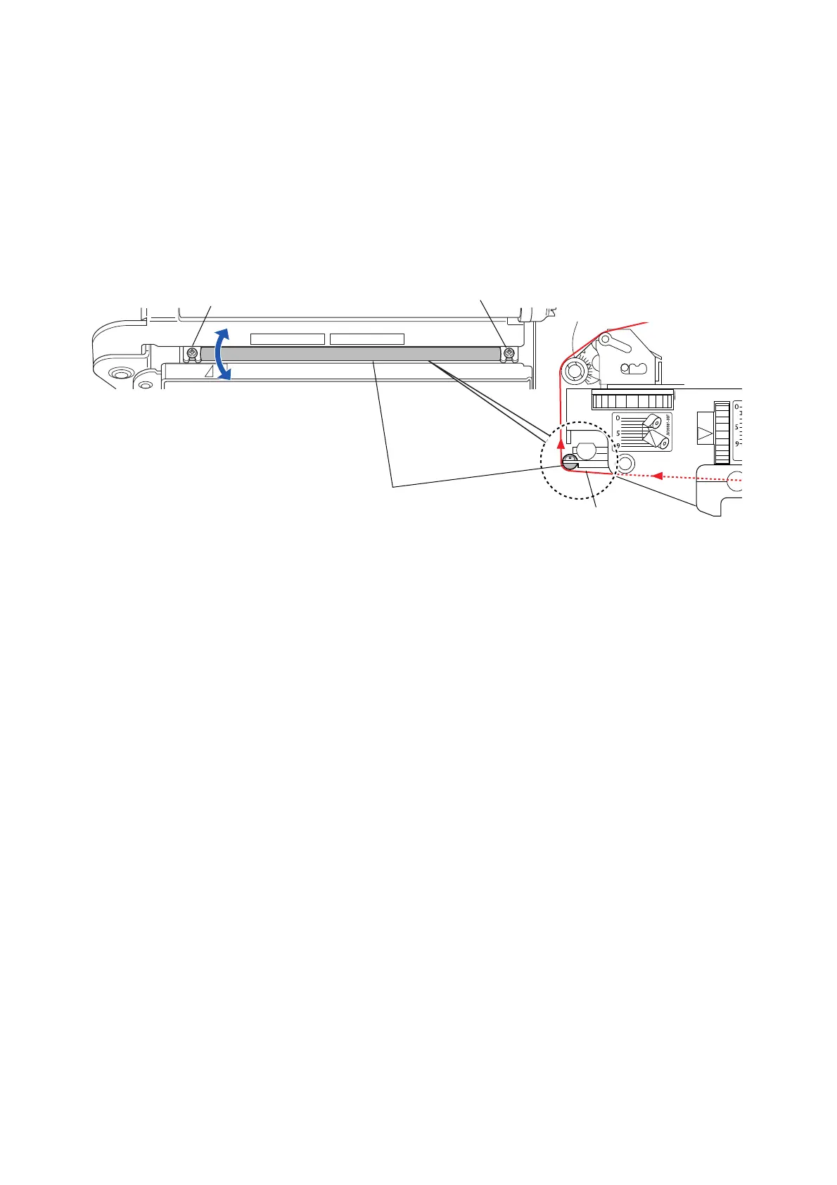
(3) Ribbon guide position adjustment (with a part of the “SA Head”)
By shifting the left end o
f the “Shaft Ribbon Guide” of the “SA Head”, ribbon wrinkle on the
front side can be corrected.
Adjustment procedure:
1. Loosen (do not remove) the screws “A” and “B”.
2. Shift the left end of the “Shaft Ribbon Guide” back and forth to move the ribbon
contacting surface.
Ribbon
A
B
(supporting point)
Shaft Ribbon Guide
[Right side view]
[Top view]

 Loading...


