Chapter 2 Operating Principles
2-2. Operation of Control Parts
CL-E700 series 2-44
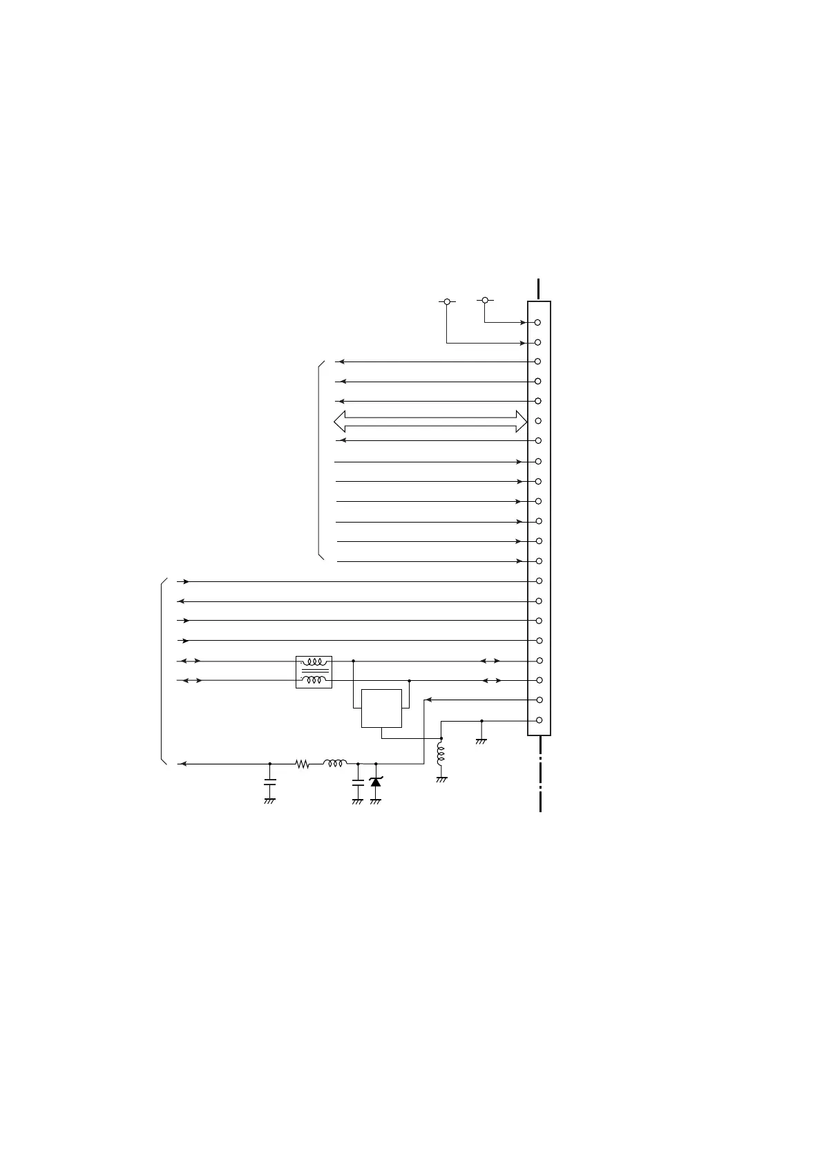
(7) Option board I/F circuit (option)
The I/F circuit of the option board supports the following interfaces.
• RS232C (Serial I/F)
• IEEE1284 (Parallel I/F)
• Ethernet I/F (Multi-function type)
• Wi-Fi I/F
Each signal of the option board is directly connected to the CPU (U1A) and the FPGA (U5). It
is controlled by the CPU and the FPGA.
To/From
U1A CPU
STB/OCI0
DATA0-7/DIPSW0-7/hEP00,hEP01
nPRIME
BUSY/RTS/pEP00
ACK/DTR/pEP01
SELECT/PPON0
PE
USB_D+
USB_D-
VBUS
TXD/SO/DIR
3
1
4
12
2
J7
SELECTIN/CST/pINT
13
14
15
AUTOFDXT/DSR
FAULT/hINT
4-11
RXD/SI
SCLK
RESET
GND
16
DWSWOT
17
18
21
22
23
24
25
26
27
33-38,40
C127
L2
C128
D4
R91
D5
L3
L4
[SA Main PCB]
Diode Array
USBDP1
USBDM1
+24V
+5V
20
28-32
nSTROBE
nSLCTIN/CTS
nATFD/DSR
nINIT/nPRIME
BUSY/RTS
nACK/DTR
SLCT
PE
IFTXD/SO/DIR
nFAULT
IFRXD/SI
IFSCLK
nRSTIF
DSWOUT
CEDAT0-CEDAT7
+24V
+5.0V
(Transient Voltage Supressor)
To/From
U5 FPGA
USBVBUS1
To Interface Board (Option)

 Loading...


