Chapter 3 Disassembly and Maintenance
3-6. Disassembly, Reassembly and Lubrication
3-27 CL-E700 series
3-6-13. Unit Mechanism
1. Remove the “Unit Ribbon”. Refer to “3-6-2 Unit Ribbon”.
2. Remove the “Unit Opepane”. Refer to “3-6-10(1) Unit Opepane”.
3. Remove the “Case” and “Cover S
teel L”. Refer to “3-6-11 Case”.
4. Remove all connectors f
rom the “SA Main PCB”. Refer to “3-6-12(1) “SA Main PCB”
Connectors”.
5. Remo
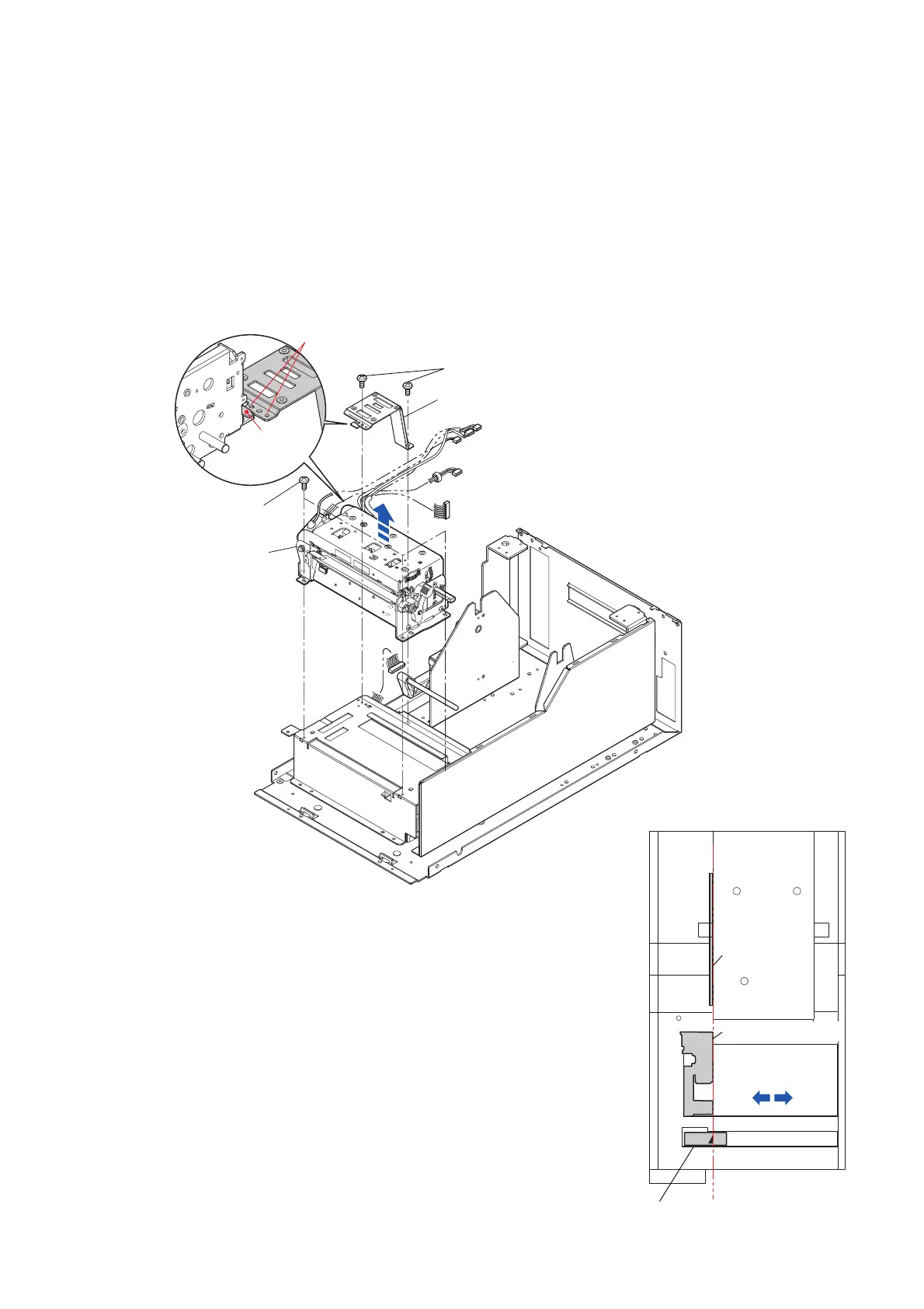
ve the 2 screws (BH M3.0x4 (NI)) and detach the “Frame Relay PCB”.
6. Remove the 3 screws (BH M3.0x6 (NI)) and detach the “Unit Mechanism” by lifting it
upwardly.
Notes on reassembling:
• Media-path left-edge alignment:
Mount the “Unit Mechanism” so that the media guide end of the
“Cover Head Wire” is aligned with the mark on the “Label Mark”
and the “Plate Holder Paper L”.
* Since the mounting holes of the “Unit Mechanism” are of
elongated ones, the “Unit Mechanism” can move right and left.
• When mounting the “Frame Relay PCB”, fit its 2 holes to the
bosses of the main body, referring to the magnified view. At this
time, be sure that the part “A” of the “Frame Relay PCB” is
correctly placed on the foot of the “Unit Mechanism”.
Cover Head Wire
Unit Mechanism
Align.
[FRONT]
Plate Holder
Paper L
Label Mark
BH M3.0x4 (NI)
BH M3.0x6 (NI)
A
Unit Mechanism
Frame Relay PCB
Holes for boss

 Loading...


