Chapter 2 Operating Principles
2-1. Operation of Each Mechanism
CL-E700 series 2-14
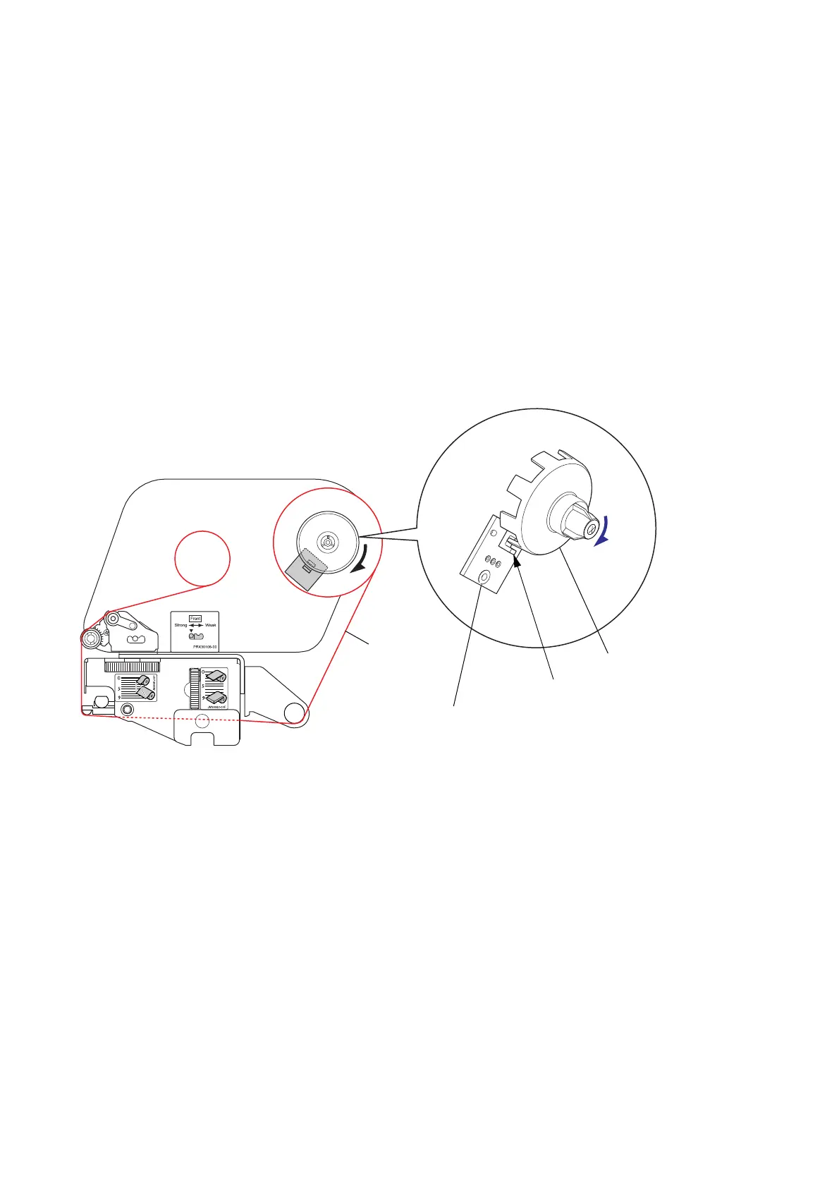
2-1-5. Ribbon Running Detection Mechanism
The major components of the ribbon running detection mechanism are:
(a) Holder Ribbon Shaft Encoder
(b) SA Ribbon Encoder (Ribbon encoder sensor)
The ribbon running is detected by using the photointerrupter on the “SA Ribbon Encoder” (Ribbon
encoder sensor) and the “Holder Ribbon Shaft Encoder” (the supply reel).
Slits are around the bottom of the “Holder Ribbon Shaft Encoder” as shown below.
When the ribbon is supplied from the supply reel, the “Holder Ribbon Shaft Encoder” turns and its
slits cross the photointerrupter. Then the photointerrupter turns ON and OFF to produce a pulse
output. The CPU of the “SA Main PCB” receives the pulse and detects the ribbon running on the
supply side.
If no pulse is output from the photointerrupter while the ribbon motor “SA Ribbon Motor F” is taking
up the ribbon, the CPU judges as the ribbon end.
Holder Ribbon Shaft Encoder
[Right side view]
Ribbon
Photointerrupter
SA Ribbon Encoder
(Ribbon Encoder Sensor)

 Loading...


