Chapter 2 Operating Principles
2-1.
Operation of Each Mechanism
2-5 CL-E700 series
2-1. Operation of Each Mechanism
This printer is comprised of the following mechanisms:
media feed/printing, label/tag detection, ribbon feed, ribbon running detection, print head up/down
detection, head balance adjustment and media thickness adjustment.
This section describes the operation of each of these mechanisms.
2-1-1. Locations and Functions of Major Electrical Parts
The following shows the locations and functions of major electrical parts.
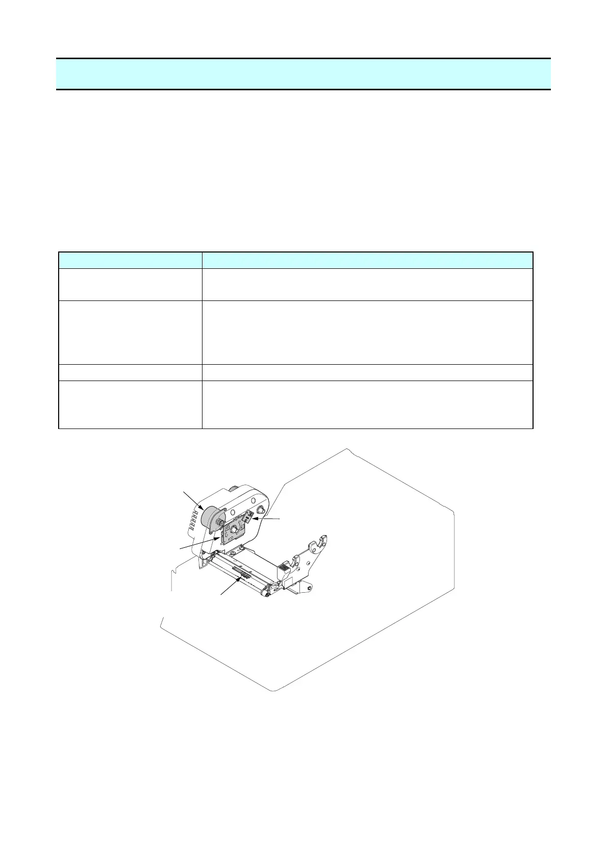
(1) “Unit Ribbon” section
Part name Description
SA Ribbon Motor F This motor takes up ribbon. A thermistor is attached to the motor
to detect the motor temperature.
SA Ribbon Sensor
(Ribbon Tension Sensor)
This sensor consists of two photointerrupters that detect the
tension applied to the take-up side ribbon. Using the sensor
output, the tension applied to the take-up side ribbon is
controlled at a constant value.
SA Ribbon Control PCB This PCB drives the “SA Ribbon Motor F” and the fan.
SA Ribbon Encoder
(Ribbon Encoder Sensor)
This sensor is a photointerrupter that detects the running state
of the supply reel. Using the sensor output, the ribbon running
state as well as the ribbon end are detected
SA Ribbon Sensor
(Ribbon Tension Sensor)
SA Ribbon Motor F
SA Ribbon Control PCB
SA Ribbon Encoder
(Ribbon Encoder Sensor)

 Loading...


