Chapter 3 Disassembly and Maintenance
3-5. Quick Detachment of Major Parts
3-9 CL-E700 series
A
B
Holder Clutch Shaft
SA Ribbon Tension Unit R
Spring Ribbon Return R
SA Ribbon Tension Unit R
[For Checking]
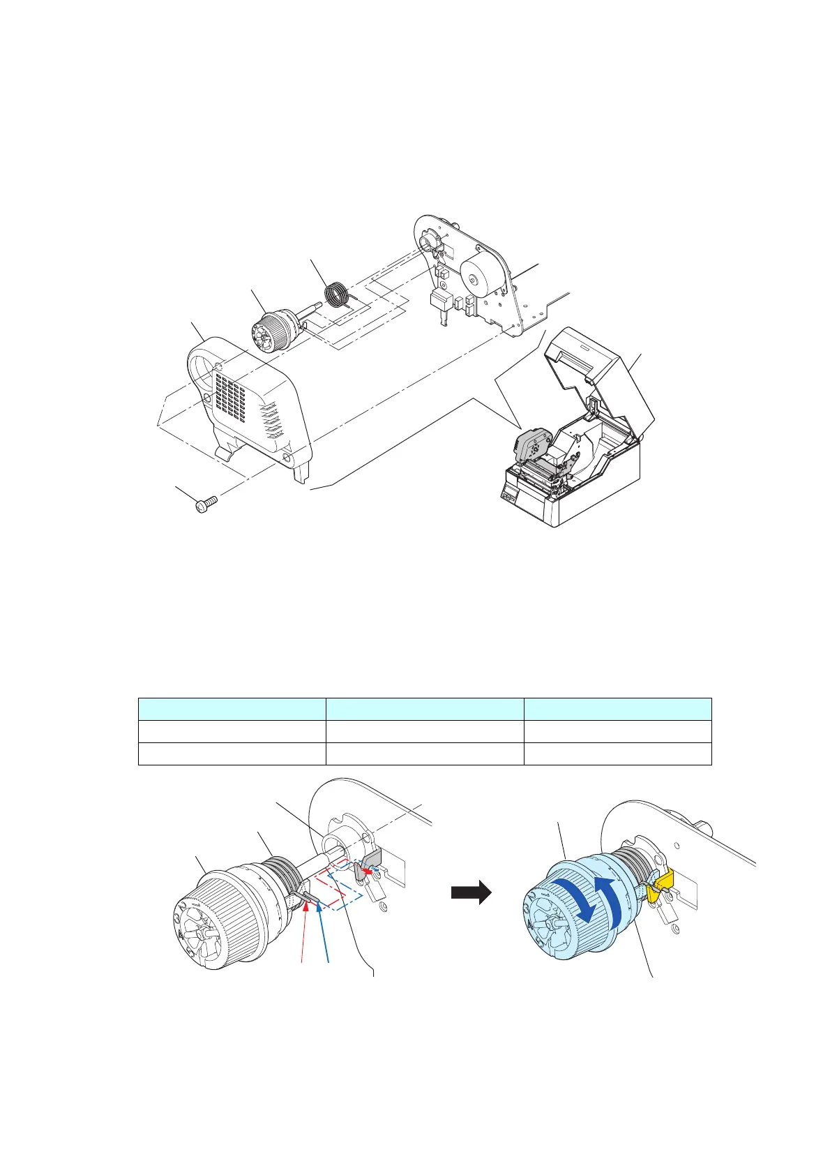
3-5-3. SA Ribbon Tension Unit R
1. Open the “SA Top Cover” Block.
2. Remove the 3 screws (BH M3.0x4 (NI)) and detach the “SA2 Ribbon Unit Fan”.
3. Remove the “Spring Ribbon Return R” from the “SA Ribbon Tension Unit R”, and detach both
from the frame.
4. Mount the “SA Ribbon Tension Unit R” as follows:
1) Hook the ends “A” and “B” of the “Spring Ribbon Return R” on each hook part of the “SA
Ribbon Tension Unit R” and “Holder Clutch Shaft”, respectively, as shown on the right side
figure.
* The “Spring Ribbon Return R” has no orientation.
The table below shows the positions where the ends “A” and “B” of the “Spring Ribbon
Return R” should be hooked on.
Spring Ribbon Return R SA Ribbon Tension Unit R Holder Clutch Shaft
End “A” Front/Upper side Front/Upper side
End “B” Rear/Lower side Rear/Lower side
2) To check for correct mounting, rotate the “SA Ribbon Tension Unit R” clockwise and
counterclockwise as shown in the above right figure to be sure that it returns to the original
position by the force of the spring “Spring Ribbon Return R”.
5. Mount the “SA2 Ribbon Unit Fan” with the 3 screws (BH M3.0x4 (NI)).
BH M3.0x4 (NI)
SA2 Ribbon Unit Fan
SA Ribbon Tension Unit R
Spring Ribbon Return R
"SA Top Cover" Block

 Loading...


