Chapter 3 Disassembly and Maintenance
3-6. Disassembly, Reassembly and Lubrication
3-25 CL-E700 series
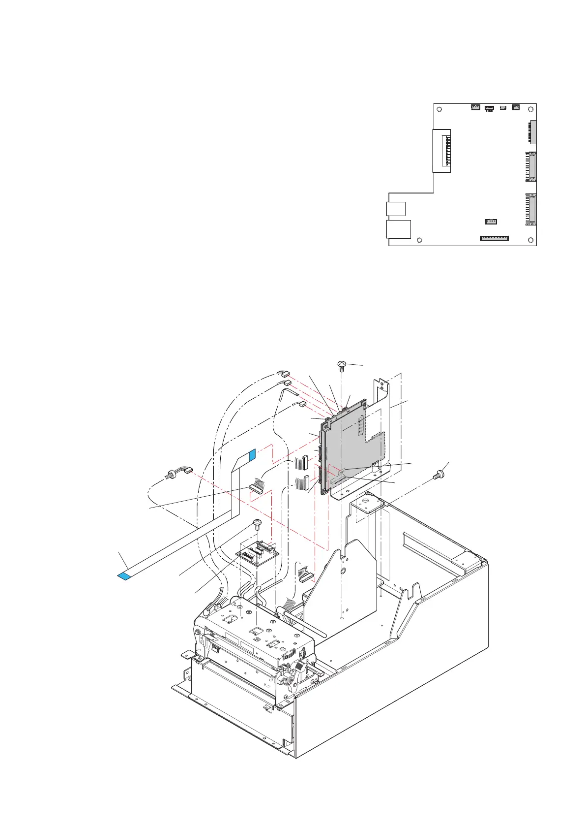
3-6-12. “SA Main PCB” and “SA Relay PCB”
(1) “SA Main PCB” Connectors
1. Remove the “Unit Ribbon”. Refer to “3-6-2 Unit Ribbon”.
2. Remove the “Unit Opep
ane”. Refer to “3-6-10(1) Unit
Opepane”.
3.
Remove the “Case” and “Cover Steel L”. Refer to “3-6-11
Case”.
4. Disconnect all conne
ctors from the “SA Main PCB”.
J2, J3 (FFC Opepane), J4, J5, J6, J8, J9, J10, J13
Note on reassembling:
• When connecting J3 (FFC Opepane), see on which side the
blue tape is, and correctly insert it in the right direction. If it
is inserted reversely, the circuit is not electrically connected.
(2) “SA Main PCB” and “SA Relay PCB”
1. Remove the 1 screw (BH M3.0
x5K) and 2 screws (BH M3.0x4 (NI)), and detach the
“SA Main PCB” Block by lifting it upwardly.
2. Disconnect the “SA Relay Cable” from the “SA Relay PCB”.
3. Remove the 4 screws (BH M3.0x4 (NI)) and detach the “SA Relay PCB”.
J13
J5
J2
J4
J3
J6
J9
J8
J10
[SA Main PCB]
J13
J5
J2
J4
J3
J6
J9
J8
J10
BH M3.0x4 (NI)
BH M3.0x5K
FFC Opepane
BH M3.0x4 (NI)
SA Relay PCB
"SA Main PCB" Block
J301
SA Relay Cable

 Loading...


