Chapter 2 Operating Principles
2-2.
Operation of Control Parts
2-41 CL-E700 series
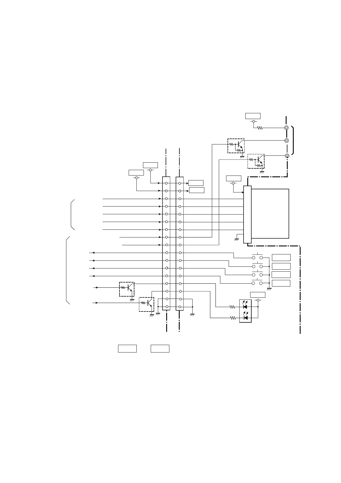
(4) Ope-pane circuit
The circuit consists of 1 LED (Green/Red), 4 switches (PAUSE, FEED, STOP and MENU) and
1 LCD.
The LCD is controlled by the signals send from the FPGA (U5). The backlight of LCD is
controlled by LCD/BKL-WHITE and LCD/BKL-ORANGE signals sent from the CPU (U1A).
The signals output from the switches are sent to the CPU.
The LED controlling signals are sent from the CPU and fed to the LED D201 via Q4 and Q5,
and the green LED (for power display) and red LED (for error display) are driven, respectively.
* In power saving mode, +3VIO and +5VIO are not supplied. For details refer to “2-2-6(1)
Power supply circuit”.
4
J3
From
U5 (FPGA)
[SA Main PCB]
SW201
SW203
SW204
SW202
D201
LCD/SI
LCD/SCLK
LCD/CD
LCD/RST
LCD/nCS
LCD/BL-W
[SA Opepane PCB]
SW/PAUSE
SW/FEED
SW/STOP
SW/MENU
LED/GREEN
LED/RED
3
4
1
4
5
2
J201
6
7
8
9
10
11
12
13
14
15
16
17
LED
Red (Error)
Q201
DTC114EM
Q202
DTC114EM
J202
LCD
PAD201
PAD202
PAD203
LCD
Backlight
BL-W
BL-O
To/From
U1A (CPU)
Anode
Cathode
(White)
Cathode
(Orange)
Green (Power)
PAUSE
FEED
STOP
MENU
LCD/BL-O
Q4
DTC114TM
Q5
DTC114TM
3
4
1
5
2
6
7
8
9
10
11
12
13
14
15
16
17
LED0_G
LED1_R
LCDDAT
LCDCD
LCDSCK
nLCDRST
nLCDCS
LCD/BKL_ORANGE
LCD/BKL_WHITE
nSW0
nSW1
nSW3
nSW2
+3VIO
+5VIO
+5VIO
R208
R209
R210
+3VIO
+5VIO
+5VIO
+3VIO

 Loading...


