Chapter 2 Operating Principles
2-2. Operation of Control Parts
CL-E700 series 2-42
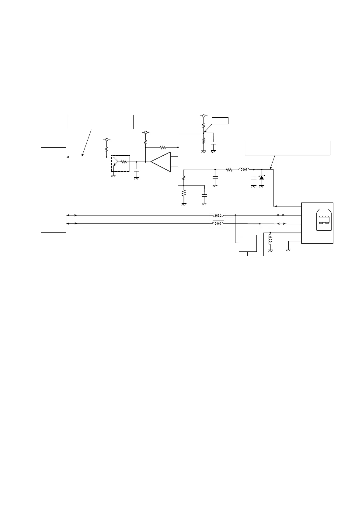
(5) USB I/F control circuit
The USB (Universal Serial Bus) I/F circuit interfaces with the USB I/F.
The comparator (U15A) and Q12 consist of a USB connection detecting circuit.
When a USB connector is connected to the printer, pin 1 (VBUS) of connector J12 goes to
“High” level. Thus, Q12 turns OFF, pin 176 (USBVBUS0) of the CPU (U1A) goes to “High” level,
and USB connection is detected.
The data transmission is carried out via pins 174 (USBDM0) and 175 (USBDP0) of the CPU.
1
2
3
4
5
D7
L6
J12
L7
C136
L5
SHLD
VBUS
GND
D-
D+
USB I/F
[SA Main PCB]
C137
D6
VBUS0
174
DM0
175
DP0
A certain voltage is applied when
a USB connector is connected.
Diode Array
(Transient Voltage Supressor)
R113
U15A
-
+
3
2
1
BA2903SFVM
R114
R115
C138
R107
R112
C134
+5.0V
Q12
DTC115TM
R109
+5.0V
C135
VBUSIN0
176
CPU
U1A
USBDM0
USBDP0
USBVBUS0
R108
+5.0V
R110
+3V
H: USB connected
L: USB disconnected
1
2
3
4

 Loading...


