Chapter 2 Operating Principles
2-2.
Operation of Control Parts
2-45 CL-E700 series
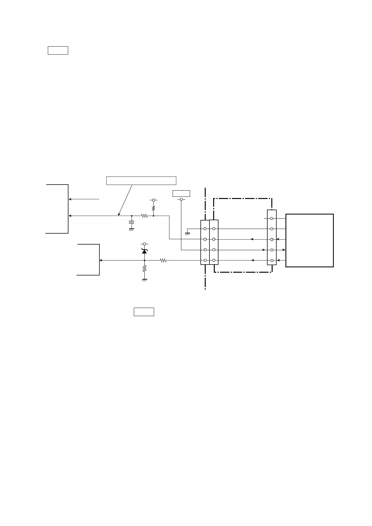
(8) Peeler circuit (for optional peeler)
+5VIO is supplied to an optional peeler.
When a peeler is installed in the printer, pin D9 (CPTYP1) is set to “Low” level. With this “Low”
level signal, the printer recognizes that the peeler is connected to. (In reality, the FPGA (U5)
judges the connected optional device (either peeler or cutter) by detecting both signals
CPTYP0 (at pin D12) and CPTYP1 (at pin D9)).
A peel sensor detects that the printed label is peeled off by the peeler. Then, the printer stops
printing. When you remove the label, the peeler sensor detects it and the printer resumes
printing.
The peel sensor output signal (analog voltage) is input to pin 101 (SNSPEEL) of the CPU
(U1A). To the CPU, two kinds of signal levels are input depending on the peeling conditions,
whether the label is peeled off or it is removed by hand.
* In power saving mode, +5VIO is not supplied. For details refer to “2-2-6(1) Power supply
circuit”.
J303
Peeler
CPTYP1
74_D9
D9
R67
C99
R68
+3.3V
D3
R69
+3.3V
R70
L: When Peeler is installed.
NC
GND
CPRTYP1
+5VIO
PEELSENS
SNSPEEL
[SA Main PCB]
3
2
1
5
4
+5VIO
OPTION_TYPE1
PEELER SENS
14
J4
15
7
14
15
7
J301
[SA Relay PCB]
3-6
3-6
AN7
CPU
U1A
FPGA
U5
101
+5VIO
CPTYP0
74_D12
D12
(from the Cutter)

 Loading...


