Chapter 3 Disassembly and Maintenance
3-7. Adjustments
CL-E700 series 3-58
(2-1) Front side “Cam Tension Base Adjust” position adjustment (For service
personnel)
1. To allow access to the “
Cam Tension Base Adjust”, detach the “Cover RBN Tension
Adjust” from the “Ribbon Sensor Frame F” Block () by removing 2 screws.
(Refer to “3-6-9(1) “Ribbon Sensor Frame F” Block”)
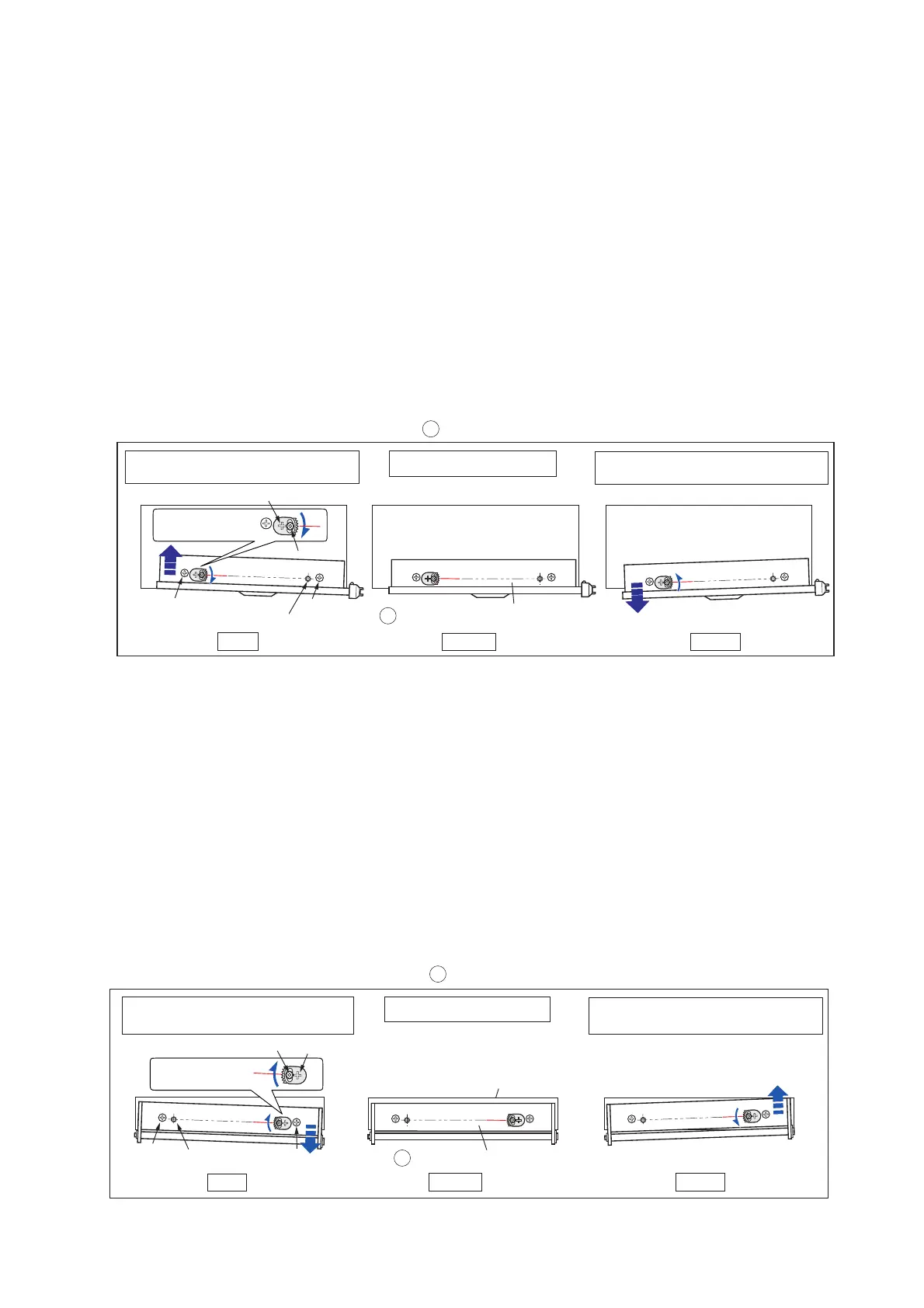
2. Loosen (do not remove) the 2 screw
s “A” shown in the figure below.
3. Loosen (do not remove) the 1 screw “B” and, by turning “C”, rotate the “Cam
Tension Base Adjust” either in the clockwise or counterclockwise depending upon
on which side the ribbon slants as viewed from the front/above.
By rotating the “Cam Tension Base Adjust”, the horizontal parallelism of the
“Ribbon Sensor Frame F” Block () (movable part) with respect to the “SA Ribbon
Frame” (fixed part) of the unit ribbon base changes.
4. Tighten the 1 screw “B” and the 2 screws “A”.
(2-2)
Rear side “Cam Tension Base Adjust” position adjustment (For user)
1.
Access to the rear side o
f the “Unit Ribbon” and loosen (do not remove) the 2
screws “A” shown in the figure below.
3. Loosen (do not remove) the 1 screw “B” and, by turning “C”, rotate the “Cam
Tension Base Adjust” either in the clockwise or counterclockwise depending upon
on which side the ribbon slants as viewed from the rear.
By rotating the “Cam Tension Base Adjust”, the vertical parallelism of the “Plate
Ribbon Guide Roller” Block () (movable part) with respect to the “SA Ribbon
Frame” (fixed part) of the unit ribbon base changes.
4. Tighten the 1 screw “B” and the 2 screws “A”.
A
B
Supporting point
"Ribbon Sensor Frame F" Block
Shifting the "Ribbon Sensor Frame F" Block ( ) (Viewing from the front/top side)
CW
Center
CCW
If left side ribbon wrinkles cannot
be eliminated by user adjustment.
Mechanical center
If right side ribbon wrinkles cannot
be eliminated by user adjustment.
A
CW: Clockwise
CCW: Counterclockwise
Base (Top side view)
(SA Ribbon Frame)
2
2
Cam Tension
Base Adjust
C
CW
Supporting point
"Plate Ribbon Guide Roller" Block
Base (Rear side view)
Center
CCW
If the left side ribbon wrinkles cannot
be eliminated viewing from the rear.
Mechanical center
A
A
(SA Ribbon Frame)
If the left side ribbon wrinkles cannot
be eliminated viewing from the rear.
Shifting the "Plate Ribbon Guide Roller" Block ( ) (Viewing from the rear side)
3
3
Cam Tension
Base Adjust
B
C

 Loading...


