Chapter 3 Disassembly and Maintenance
3-6. Disassembly, Reassembly and Lubrication
3-45 CL-E700 series
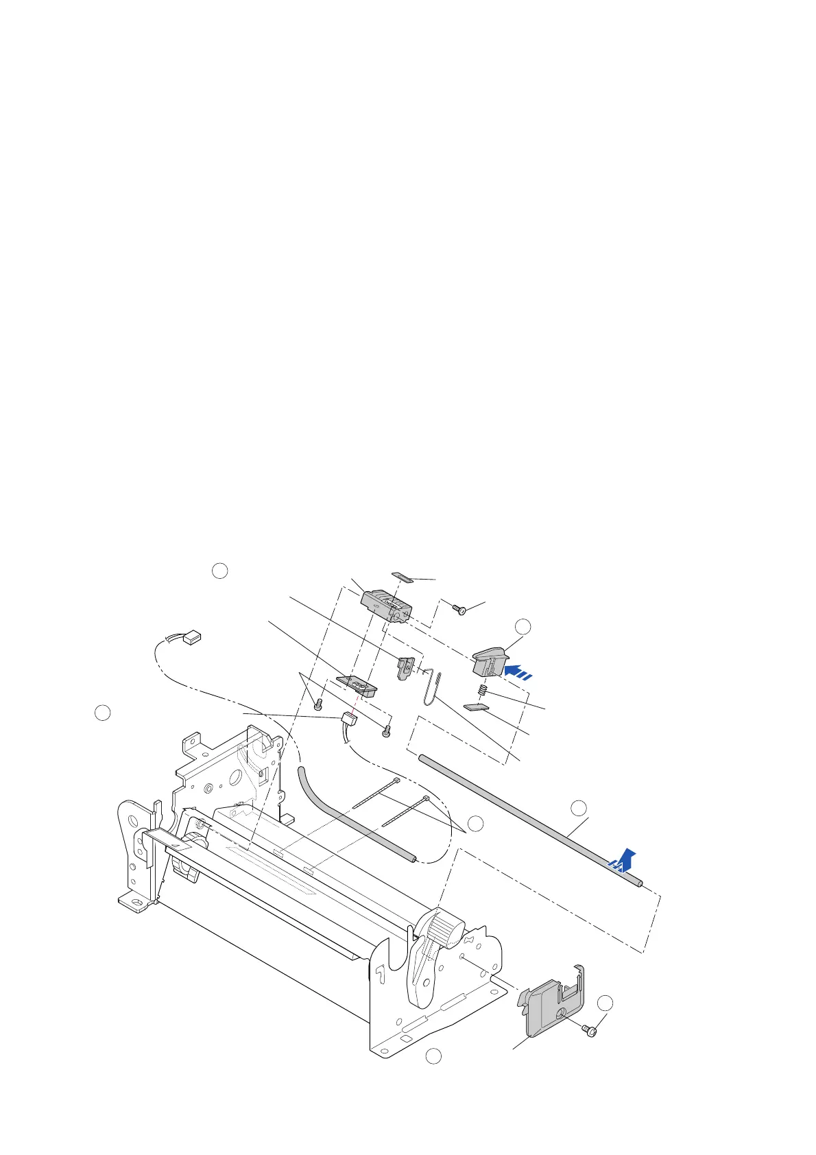
3-6-21. “SA Ref Sensor PCB” and “Spring Adjust Sensor L”
1. Remove the “Unit Ribbon”. Refer to “3-6-2 Unit Ribbon”.
2. Remove the “Unit Opepane”. Refer to “3-6-10(1) Unit Opepane”.
3. Remove the “Case” and “Cover S
teel L”. Refer to “3-6-11 Case”.
4. Remove all connectors f
rom the “SA Main PCB”. Refer to “3-6-12(1) “SA Main PCB”
Connectors”.
5. Remo
ve the “Unit Mechanism”. Refer to “3-6-13 Unit Mechanism”.
6. Access to the bottom of the “Unit Mechanism”, a
nd disconnect the connector of the “SA Ref
Sensor Cable” () from the “SA Ref Sensor PCB”.
7. Remove the 1 screw (BH M3.0x4 (NI)) () and detach the “Holder Guide Sensor L” ().
8. Slide the “Guide Paper Set” () to the left, and pull out the “Shaft Sensor Guide” () (with
the “Guide Paper Set” () and “Holder Adjust Sensor L” ()) in the direction of the arrow.
9. Pull out the “Guide Paper Set” () from the “Shaft Sensor Guide” (), and detach the
“Spring Friction Sen PG” and “Plate Friction PG” from it.
10. Pull out the “Holder Adjust Sensor L” () from the “Shaft Sensor Guide” (), and then
detach the following parts.
1) Remove the 2 screws (NO.0 PHT(BT#1) M2.0x3) and detach the “SA Ref Sensor
PCB”.
2) Remove the 1 screw (NoO PH(4-0.3) M2x3 (NI)), and detach the “Plate Adj Sen L
Spring” and “Spring Adjust Sensor L”.
3) Peel off the “Cover Paper Sensor”.
11. Cut the 2 wire ties “Wire Tie” () and remove the “SA Ref Sensor Cable” ().
J8
Shaft Sensor Guide
6
5
1
2
3
4
BH M3.0x4 (NI)
Holder Guide Sensor L
Cover Paper Sensor
Holder Adjust Sensor L
NoO PH(4-0.3) M2x3 (NI)
Guide Paper Set
Spring Friction Sen PG
Plate Friction PG
Spring Adjust Sensor L
Plate Adj Sen L Spring
NO.0 PHT(BT#1)
M2.0x3
Wire Tie
SA Ref Sensor PCB
SA Ref Sensor Cable
7

 Loading...


