Chapter 3 Disassembly and Maintenance
3-6. Disassembly, Reassembly and Lubrication
3-39 CL-E700 series
3-6-19. “SA Head”, “Cam Head Adjust” and “Cam Head Balance”
When detaching or reinstalling the “SA Head”, be careful not to damage the thermal
elements. Especially, avoid contacting the thermal elements with a metal part, etc.
Do not touch the thermal elements of the “SA Head” with your bare hand.
(1) “SA Head” Block
1. Remove the “Unit Ribbon”. Refer to “3-6-2 Unit Ribbon”.
2. Remove the “Unit Opep
ane”. Refer to “3-6-10(1) Unit Opepane”.
3. Remove the “Case” and “Cover S
teel L”. Refer to “3-6-11 Case”.
4. Remove all connectors f
rom the “SA Main PCB”. Refer to “3-6-12(1) “SA Main PCB”
Connectors”.
5. Remo
ve the “Unit Mechanism”. Refer to “3-6-13 Unit Mechanism”.
6. Remove the “Unit Head”. Refer to “
3-6-18 “Unit Head” and “Unit PF””.
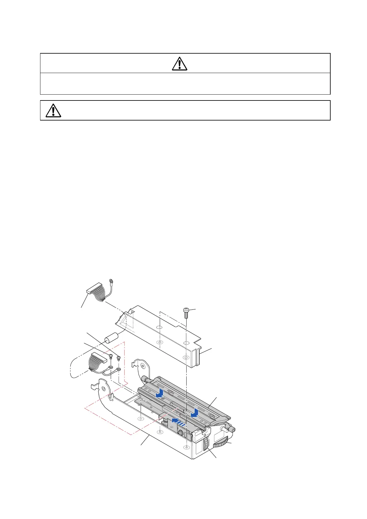
7. Place the “Unit Head” upside down a
s shown below.
8. Remove the 2 screws (BH M3.0x6 (NI)) and detach the “Guide Head Cable”.
9. To make removal easy, set both dials (Media width adjustment dial and Media
thickness adjustment dial) to “5”.
10. While pressing down the “SA Head” Block, first move it forward and then to the left to
remove it. Refer to the arrows in the figure.
11. Disconnect the connector from the “SA Head” Block, remove the 2 screws (BH M3.0x3
(NI) and BH M3.0x6 (NI)), and remove the “SA Head Cable”.
Caution
BH M3.0x6 (NI)
Guide Head Cable
Unit Head
SA Head Cable
BH M3.0x6 (NI)
BH M3.0x3 (NI)
(Media Width Adjustment Dial)
(Media Thickness Adjusment Dial)
"5"
"5"
"SA Head" Block

 Loading...


