Chapter 2 Operating Principles
2-1.
Operation of Each Mechanism
2-11 CL-E700 series
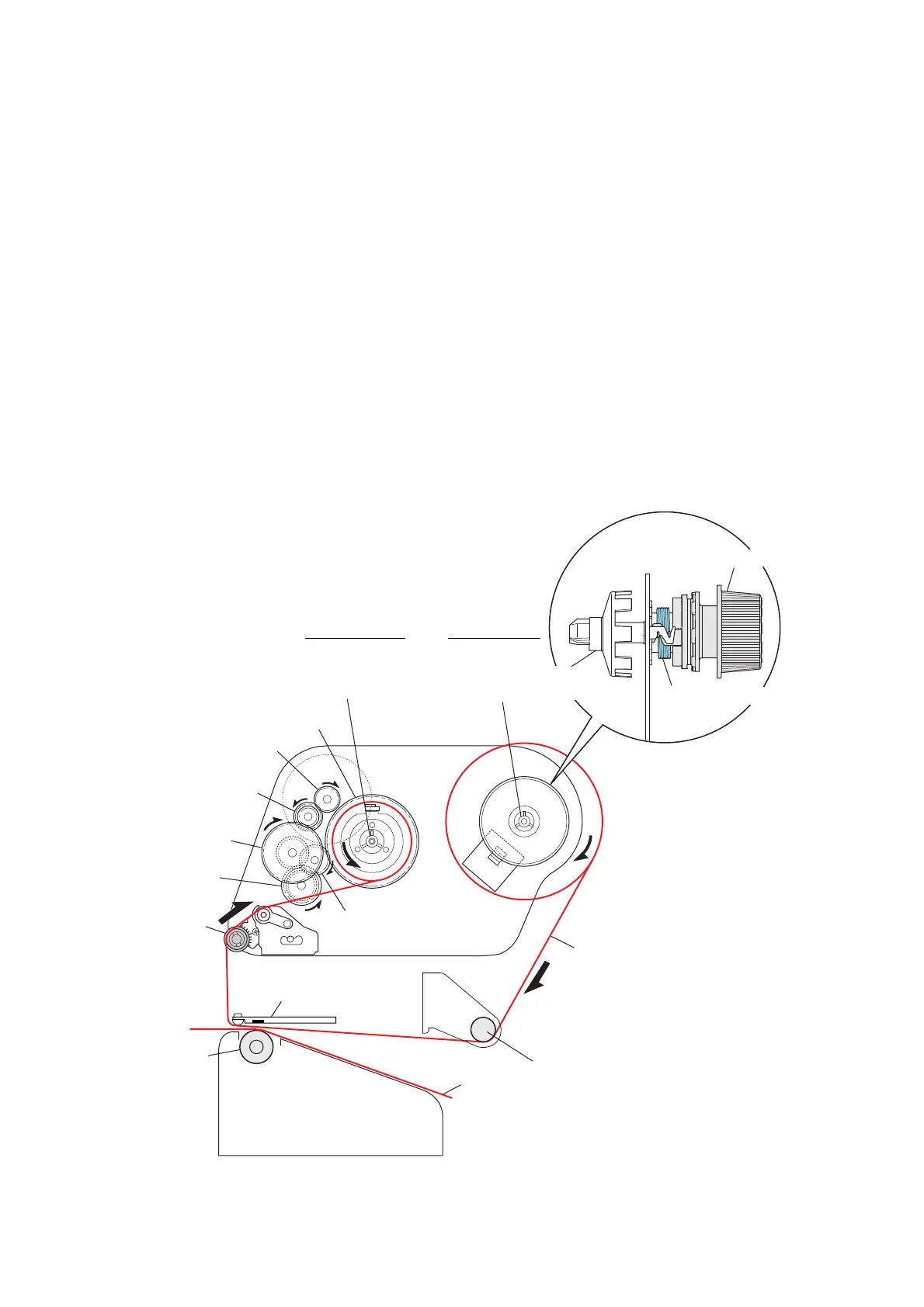
2-1-4. Ribbon Feed Mechanism
The major components of the ribbon feed mechanism are:
(a) SA Ribbon Motor F (d) SA Ribbon Tension Unit R
(b) SA Ribbon Tension Shaft F (e) Ribbon gear train
(c) SA Ribbon Sensor (Ribbon tension sensor)
Ink ribbon is set to the take-up reel (SA Holder R Shaft) and the supply reel (Holder Ribbon Shaft
Encoder) via the supplied ribbon holders.
As the ribbon motor “SA Ribbon Motor F” on the take-up side turns in the direction shown in the
figure, the take-up reel (Gear 5F Ribbon) is driven via the “Gear Reduction Ribbon 1”, “Gear 2
Ribbon”, “Gear 3 Ribbon” and “Gear 4 Ribbon”.
The ribbon is supplied from the supply reel via the “Roller Ribbon Guide R” and “SA Ribbon
Tension Shaft F”, and then taken up.
A back tension generating mechanism that is formed by the “SA Ribbon Tension Unit R” and
“Sprint Ribbon Return R” is directly connected to the supply reel. When the ribbon is supplied, the
back tension generating mechanism gives an appropriate back tension to the ribbon.
Gear 5F Ribbon
Gear Reduction Ribbon 1
Gear 2 Ribbon
Gear 3 Ribbon
SA Ribbon Motor F
SA Ribbon
Tension Shaft F
Media
Roller Ribbon Guide R
SA Platen
SA Head
Taku-up Side
Supply Side
Spring Ribbon Return R
SA Ribbon Tension Unit R
Take-up Reel
(SA Holder R Shaft)
[Back Tension Generation Mechanism]
Gear 4 Ribbon
Supply Reel
(Holder Ribbon Shaft Encoder)
[Right side view]
Ribbon

 Loading...


