Chapter 3 Disassembly and Maintenance
3-6. Disassembly, Reassembly and Lubrication
3-49 CL-E700 series
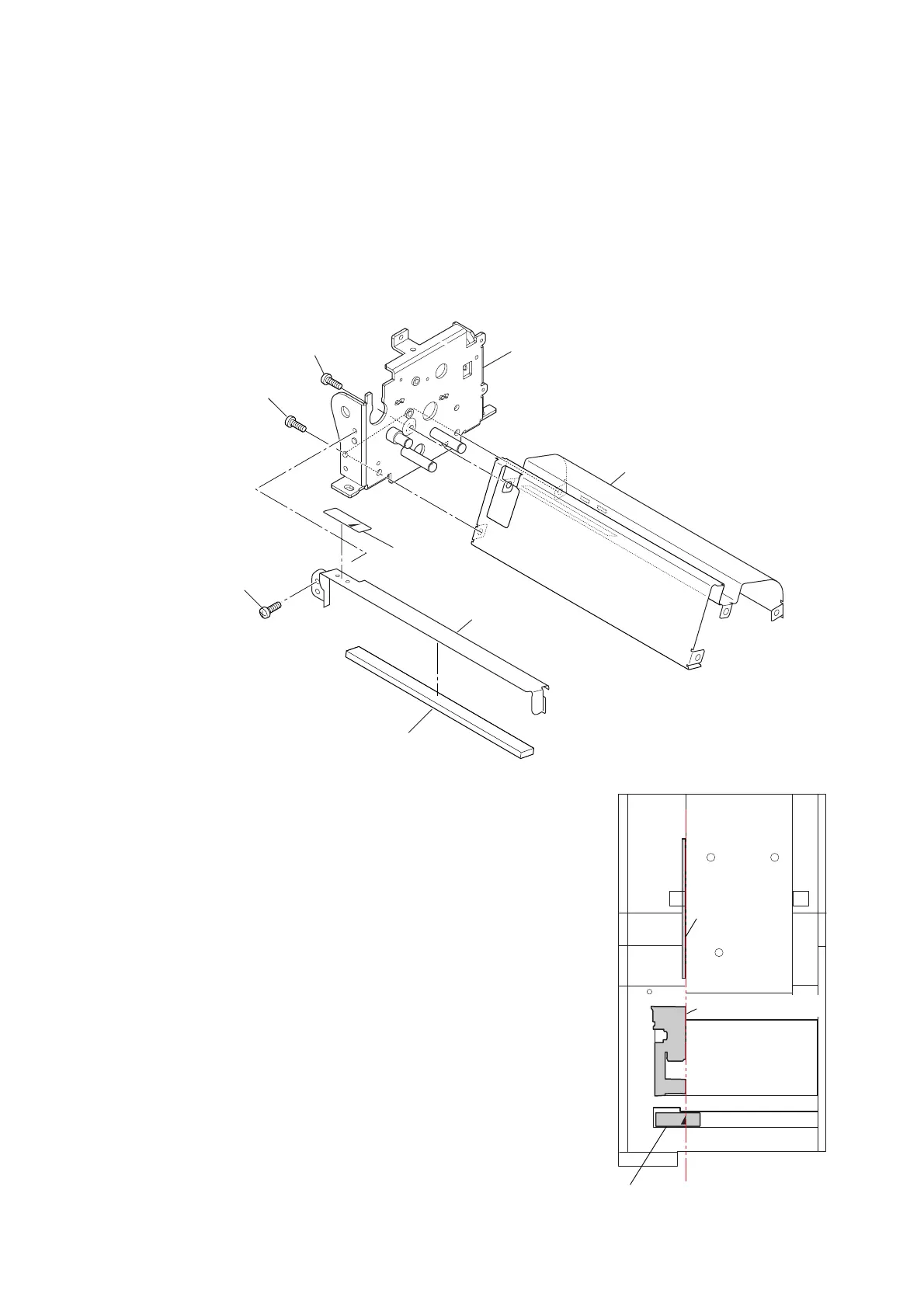
(3) “Frame Main”, “SA Main Plate L” and “Plate Peeler”
1. Remove the 2 screws (B
H M3.0x4 (NI)) and 1 screw (NO0 TFH M2.6x4 (NI)), and
detach the “Frame Main”.
2. Remove the 1 screw (BH M3.0x4 (NI)) and detach the “Plate Peeler” Block from the
“SA Main Frame L”.
Tips: The “Plate Peeler” Block can be removed by simply opening the “SA Top Cover”
Block.
3. Peel off the “Label Mark”, and remove the “Sponge Peeler Plate” from the “Plate
Peeler”.
Note on reassembling:
• Stick the “Label Mark” so that its mark is aligned with the
media guide end of the “Cover Head Wire” (a part of the
“Unit Mechanism”).
NO0 TFH M2.6x4 (NI)
BH M3.0x4 (NI)
BH M3.0x4 (NI)
Sponge Peeler Plate
Plate Peeler
Label Mark
Frame Main
SA Main Frame L
Cover Head Wire
Unit Mechanism
Align.
[FRONT]
Plate Holder
Paper L
Label Mark

 Loading...


