Chapter 2 Operating Principles
2-2.
Operation of Control Parts
2-23 CL-E700 series
2-2-4. Sensors
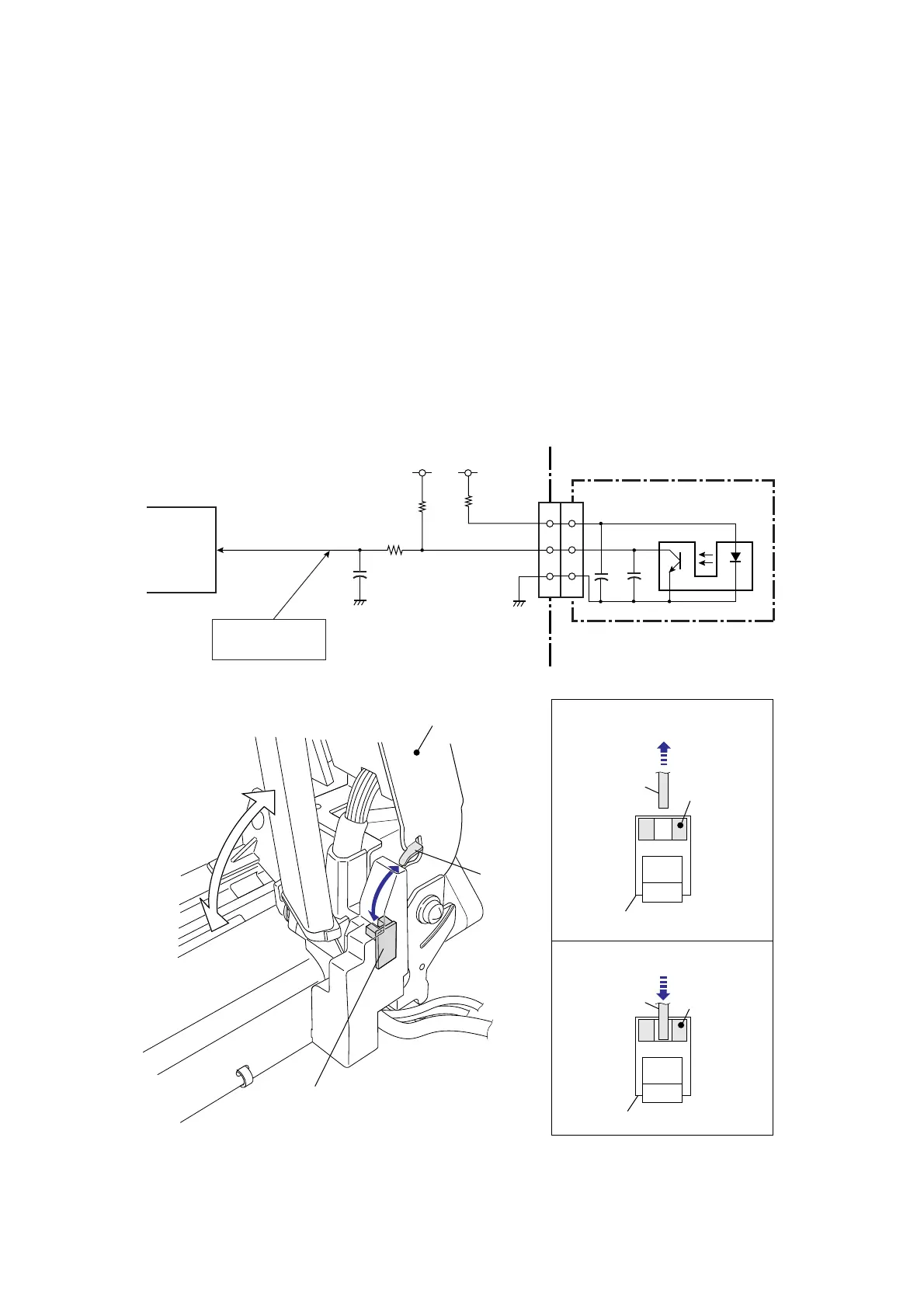
(1) Head up sensor (SA Head Up Sensor PCB)
The head up sensor is used to detect the head position (up or down). This sensor uses a
photointerrupter.)
When the head block is closed (in the down position), the projection “A” of the head block is
engaged in the head up sensor, and the light emitted from the LED of the photointerrupter is
blocked by the projection “A”. Thus, the phototransistor turns OFF, and pin 24 (HDUSENS) of
the CPU (U1A) goes to “High” level.
When the head block is opened (in the up position), the projection “A” is disengaged from the
head up sensor, and the light emitted from the LED reaches the phototransistor. Thus, the
phototransistor turns ON and pin 24 (HDUSENS) of the CPU goes to “Low” level.
When the head block is opened, the LED on the operation panel blinks in red and the LCD
displays “Error Head Open”. Then, the printer goes off-line.
U1A
CPU
2
3
1
+3.3V
HDUSENS
J10
R106
R104
C133
24
+3.3V
R105
L: Head Up
H: Head Down
2
3
1
CN201
P6_4
[SA Main PCB]
[SA Head Up Sensor PCB]
Head Up Sensor
SA Head Up Sensor PCB
(Head Up Sensor)
Head Block "Up" position
Head Block "Down" position
Head Block
SA Head Up Sensor PCB
SA Head Up Sensor PCB
Photo-
Interrupter
Photo-
Interrupter
A
A
A

 Loading...


