Chapter 3 Disassembly and Maintenance
3-6. Disassembly, Reassembly and Lubrication
3-33 CL-E700 series
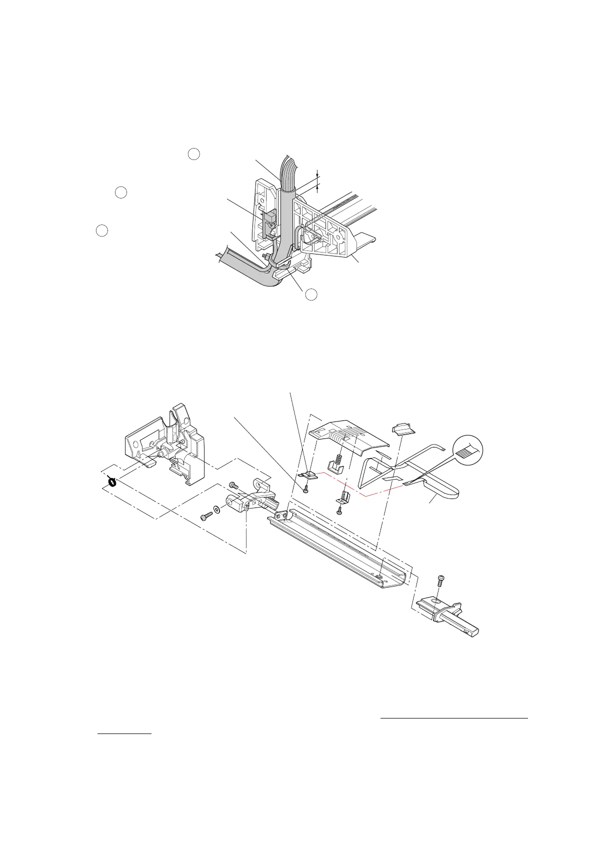
• Referring to the following figure, mount the “SA Head Cable” () and “SA Head Up
Sensor PCB” () (with the “SA Head Up Sensor Cable” ()) on the “Cover Head Wire”,
and tie them with the “Wire Tie” ().
At this time, mount the “SA Head Cable” () so that the distance between its tube end
and the top of the “Cover Head Wire” is 0 to 5mm (0 to 0.2 inches) as shown below.
(2) SA TRA Sen PCB
1.
Remove the 1 screw (NO.0
TFH (PT4-0.5) M2.0x4), detach the “SA TRA Sen PCB”,
and disconnect the “FFC TRA Sensor” from the “SA TRA Sen PCB”.
Notes on reassembling:
• Correctly insert the “FFC TRA Sensor” in the correct direction, referring to the magnified
view in the above figure. If it is inserted upside down, the circuit is not electrically
connected.
• When the “SA TRA Sen PCB” is replaced with a new one, be sure to perform the sensor
adjustment. Refer to “3-7-1 Transparent/Reflective Sensor Adjustment”.
SA Head Up Sensor PCB
SA Head Up Sensor Cable
Wire Tie
SA Head Cable
6
5
3
4
0 to 5mm (0 to 0.2 inches)
Cover Head Wire
NO.0 TFH (PT4-0.5)
M2.0x4
SA TRA Sen PCB
FFC TRA Sensor

 Loading...


