Chapter 2 Operating Principles
2-1. Operation of Each Mechanism
CL-E700 series 2-12
Taking up the ribbon on the take-up side:
Ribbon is taken up on the take-up side in the sequence shown below. (See the figure on the
previous page.)
* Details of ribbon tension control on the take-up side are explained in “Detecting ribbon tension
(Ribbon tension sensor)” on the next page.
(1) As the media is fed, the ribbon is also fed by a friction force produced between the media and
the “SA Head”, and the ribbon on the take-up side slacks accordingly.
(2) As the ribbon slacks, the “SA Ribbon Tension Shaft F” is pushed outward by the internal
springs and the ribbon tension sensor (SA Ribbon Sensor) turns OFF.
(3) As the ribbon tension sensor turns OFF, the “SA Ribbon Motor F” rotates faster to take up the
slackened ribbon.
(4) As the ribbon tightens, the “SA Ribbon Tension Shaft F” is pushed inward by the ribbon and the
ribbon tension sensor turns ON.
(5) As the ribbon tension sensor turns ON, the “SA Ribbon Motor F” rotates slower to take up the
tightened ribbon.
* Although the ribbon holder is directly connected to the take-up reel, since it incorporates a
spring mechanism, the ribbon is also taken up via this spring mechanism.
Supplying the ribbon on the supply side:
As the media is fed, the ribbon on the supply side is fed together with the media. Thus, the ribbon
is supplied from the supply reel. To the supply reel, the back tension generating mechanism
(consisting of the “SA Ribbon Tension Unit R” and “Spring Ribbon Return R”) is directly connected.
As the ribbon is pulled and the supply reel turns, a reversely-directed force is generated in the “SA
Ribbon Tension Unit R” of the back tension generating mechanism to give an adequate back
tension to the ribbon.
* Although the ribbon holder is directly connected to the supply reel, since it incorporates a spring
mechanism, the ribbon is also supplied via this spring mechanism.
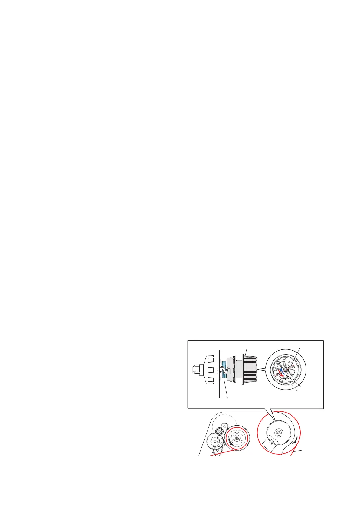
The “SA Ribbon Tension Unit R” incorporates a clutch mechanism and the tension is adjustable
with the parallel pin inside the adjust knob. Numbers “1” to “5” are marked on the adjust knob and
the tension changes by changing the position of the parallel pin as follows.
“1”: The weakest tension
|
“5”: The strongest tension
* When shipping, the parallel pin is set to “4”.
The printer is designed to obtain an optimum
tension by changing the position of the parallel pin.
For wider ribbon (4 inches, etc.), set to “4” as a
rough indication to give a strong tension.
For narrower ribbon (2 inches, etc.), set to “2” as a
rough indication to give weak tension.
Spring Ribbon Return R
SA Ribbon Tension Unit R
[Back Tension Generation Mechanism]
4: Factory set value
Parallel Pin
Strong
Weak
Ribbon

 Loading...


