Chapter 3 Disassembly and Maintenance
3-6. Disassembly, Reassembly and Lubrication
CL-E700 series 3-46
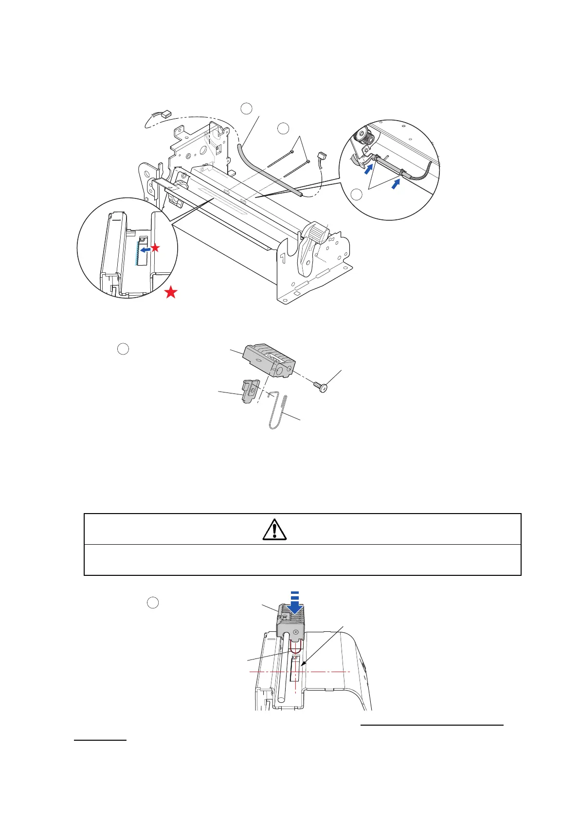
Notes on reassembling:
• Apply FLOIL G-311S along the tooth side of the slit as shown below.
• Tie the “SA Ref Sensor Cable” () with the 2 wire ties “Wire Tie” () as shown below.
• When mounting the “Plate Adj Sen L Spring” and “Spring Adjust Sensor L”, direct them as
shown below.
• When mounting the shaft “Shaft Sensor Guide” () (with the “Guide Paper Set” () and
“Holder Adjust Sensor L” (), align both ends of the shaft in place.
At this time, press down the “Holder Adjust Sensor L” () by pushing its top to insert the
“Spring Adjust Sensor L” into the slit. (Since the width of the “Spring Adjust Sensor L” is wider
than that of the slit, it is required to push in.
Push straight down the “Holder Adjust Sensor L” ().If it is pushed slantwise,
the “Spring Adjust Sensor L” can be damaged.
• When the “SA Ref Sensor PCB” is replaced with a new one, be sure to perform the sensor
adjustment. Refer to “3-7-1 Transparent/Reflective Sensor Adjustment”.
5
Holder Adjust Sensor L
NoO PH(4-0.3) M2x3 (NI)
Spring Adjust Sensor L
Plate Adj Sen L Spring
Caution
Spring Adjust Sensor L
5
Press straight down.
Slit
Holder Adjust Sensor L
J8
6
Wire Tie
SA Ref Sensor Cable
7
6
Wire Tie
FLOIL G-311S

 Loading...


