Chapter 3 Disassembly and Maintenance
3-6. Disassembly, Reassembly and Lubrication
CL-E700 series 3-26
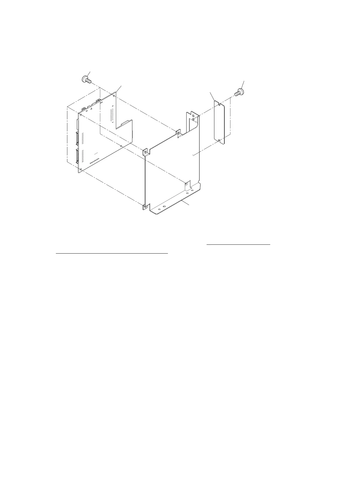
4. Remove the 4 screws (BH M3.0x4 (NI)) and detach the “SA Main PCB”.
5. Remove the 2 screws (BH M3.0x4 (NI)) and detach the “Plate I/F Cover” from the
“Plate Main PCB”.
Note on reassembling:
• When the “SA Main PCB” is replaced with a new one, be sure to perform the
transparent/reflective sensor adjustment. Refer to “3-7-1 Transparent/Reflective Sensor
Adjustment”.
BH M3.0x4 (NI)
BH M3.0x4 (NI)
Plate Main PCB
SA Main PCB
Plate I/F Cover

 Loading...


