NGT—Technical description (2010)
NGT Transceiver System Technical Service Manual 73
RF unit
The supply voltages for the RF unit are shown in Table 21 to Table 25.
Drawing 04-03109
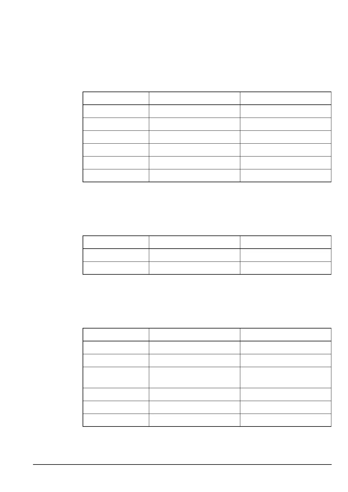
Table 21: Supply voltages for the Audio Interface PCB in the RF unit
Supply Description Source
A Unregulated battery supply via Filter and Control PCB
A (protected) 2 A current-limited battery IC14
+10 V +10 V regulated supply IC9
+5 V +5 V regulated supply IC10
+5 VQ +5 V quiet for opamp bias IC10 (filtered)
+6 VSBY +6.2 V standby for CIB IC4, D9, D10
Drawing 04-03108 (sheet 1)
Table 22: Supply voltages for the Application Processor PCB in the RF unit
Supply Description Source
+5 V +5 V switchmode supply IC6
VREF +2.5 V reference voltage IC5
ALTERNATIVE TEXT
Drawing 04-03106 (sheet 1)
Table 23: Supply voltages for the RF/IF PCB in the RF unit (04-03106)
Supply Description Source
A Unregulated battery supply via Audio Interface PCB
+5 V +5 V regulated supply IC210
+26 V +26 V from charge pump
supply
IC402
+10 V +10 V regulated supply via Audio Interface PCB
+10 VRx +10 V In Rx V419, V420
+10 VTx +10 V In Tx V421, V422