NGT—Checks and adjustments
NGT Transceiver System Technical Service Manual 167
Aligning the 45 MHz filters
Aligning the Rx filter
To align the 45 MHz Rx filter:
1 Connect a signal generator to the receiver input of the transceiver.
1 Set the signal generator to 8.4 MHz at –40 dBm (2 mV).
1 Connect a 10× probe on channel 1 of an oscilloscope to TP201 on the RF/IF PCB.
1 Set the channel 1 input to AC at 20 mV per division (200 mV per division with 10×
probe).
1 Set the timebase of the oscilloscope to 5 ms per division.
1 Connect the TRIG test point on the RF/IF PCB to the external trigger of the
oscilloscope.
1 Set the oscilloscope for an external positive trigger and adjust for lock.
1 Set the transceiver to channel 4 to initiate the receive sweep test.
1 Adjust the trace to the centre position.
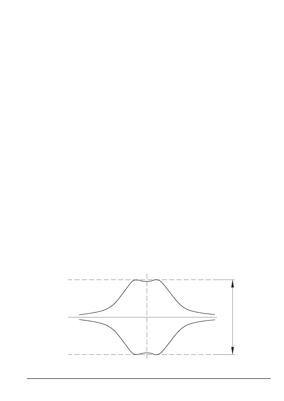
1 Adjust T104, L110, L111 and T105 for a flat response as shown in Figure 38.
Figure 38: Receive sweep test display
ALTERNATIVE TEXT
Drawing 08-05261 (sheet 2) or 08-05889 (sheet 2)
NOTE If the PCB issue status is -06 or earlier, see drawing 08-05889 (sheet 2).
NOTE
The transceiver must be in Service mode to perform this check (see
page 154, Accessing Service mode).
NOTE With 08-05889, spikes on the waveform are normal.
1 Volt
Approx