3012—Overview and specifications
298 NGT Transceiver System Technical Service Manual
The CTS and RTS lines provide hardware flow control between the data modem and the
terminal or PC.
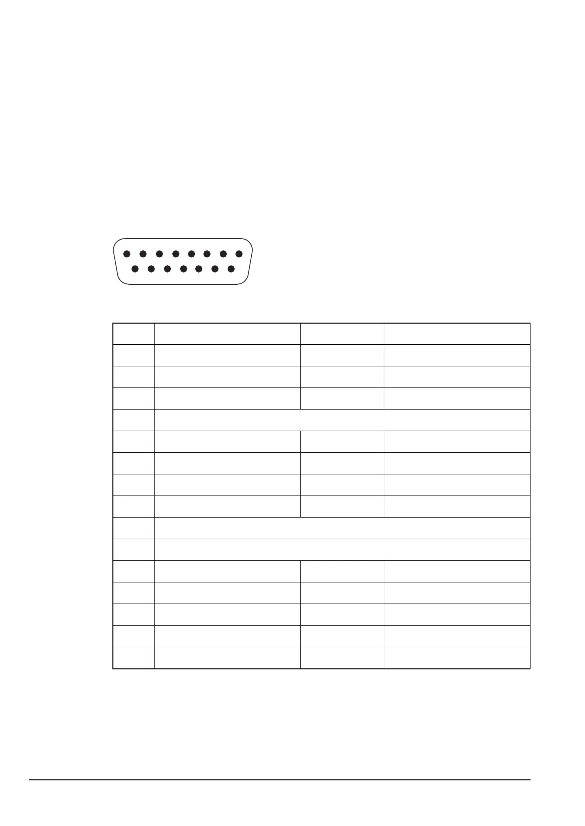
Pinouts of the Transceiver connector on the 3012
The Transceiver connector is a 15-pin D-type socket used to connect the data modem
to the transceiver. This interface also supplies switched DC power from the transceiver to
the data modem.
Figure 4: Front view of the Transceiver connector on the 3012
Table 2: Pinouts for the Transceiver connector on the 3012
Pin no. Function Input/output Signal description
1 Power supply Input +12 V
2 Power supply Input +12 V
3 Serial control data Tx Output TTL
4N/C
5 Quiet Output +12 V when in data mode
6 Busy Output OC
7 PTT Output OC
8 Audio Output 3 V p−p max
9 Ground
10 Ground
11 Scan Input
12 Spare
13 Busy Input
14 Serial control data Rx Input TTL
15 Audio Input 4 V p–p max
18
915