NGT—Overview and specifications
NGT Transceiver System Technical Service Manual 43
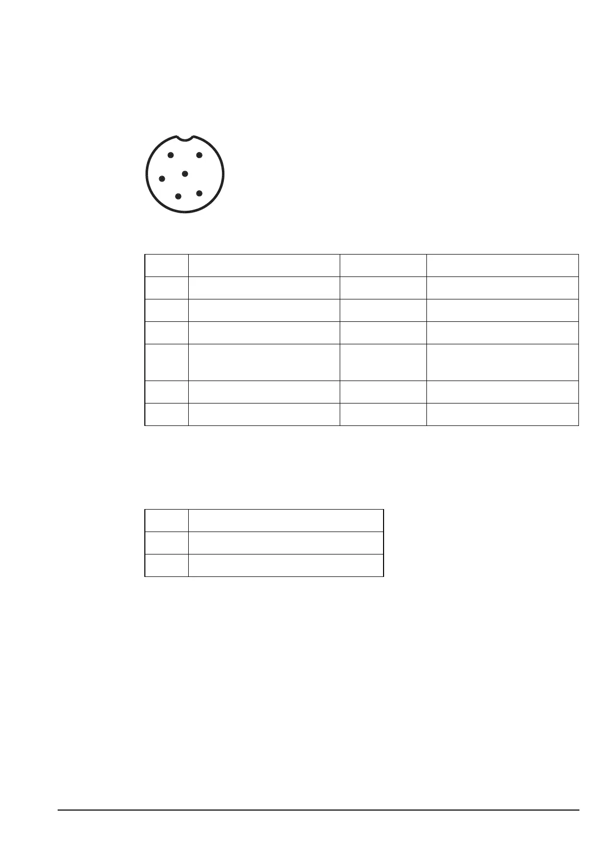
Pinouts of the antenna control connector on the RF unit
Figure 7: Front view of the antenna control connector on the RF unit
Pinouts of the DC supply connector on the RF unit
RF connector
The RF connector is a flying lead located on the right side of the rear panel. It is used to
connect to an antenna.
Table 5: Pinouts of the antenna control connector on the RF unit
Pin no. Function Input/output Signal level
1 Tune in/out Input/output 5 V logic, active low
2 Scan Output Active low (open collector)
3 Tuned in Input 5 V logic
4 A rail protected (1 to 2 A)
nominal
Output +13.6 V nominal
5 External ALC input Input Control at 3.6 V
6 Ground 0 V
Table 6: Pinouts of the DC supply connector on the RF unit
Pin no. Function
1 +12 V nominal (10.8 to 16 V DC)
2 Ground
1
2
3
4
5
6