High power—Overview and specifications
212 NGT Transceiver System Technical Service Manual
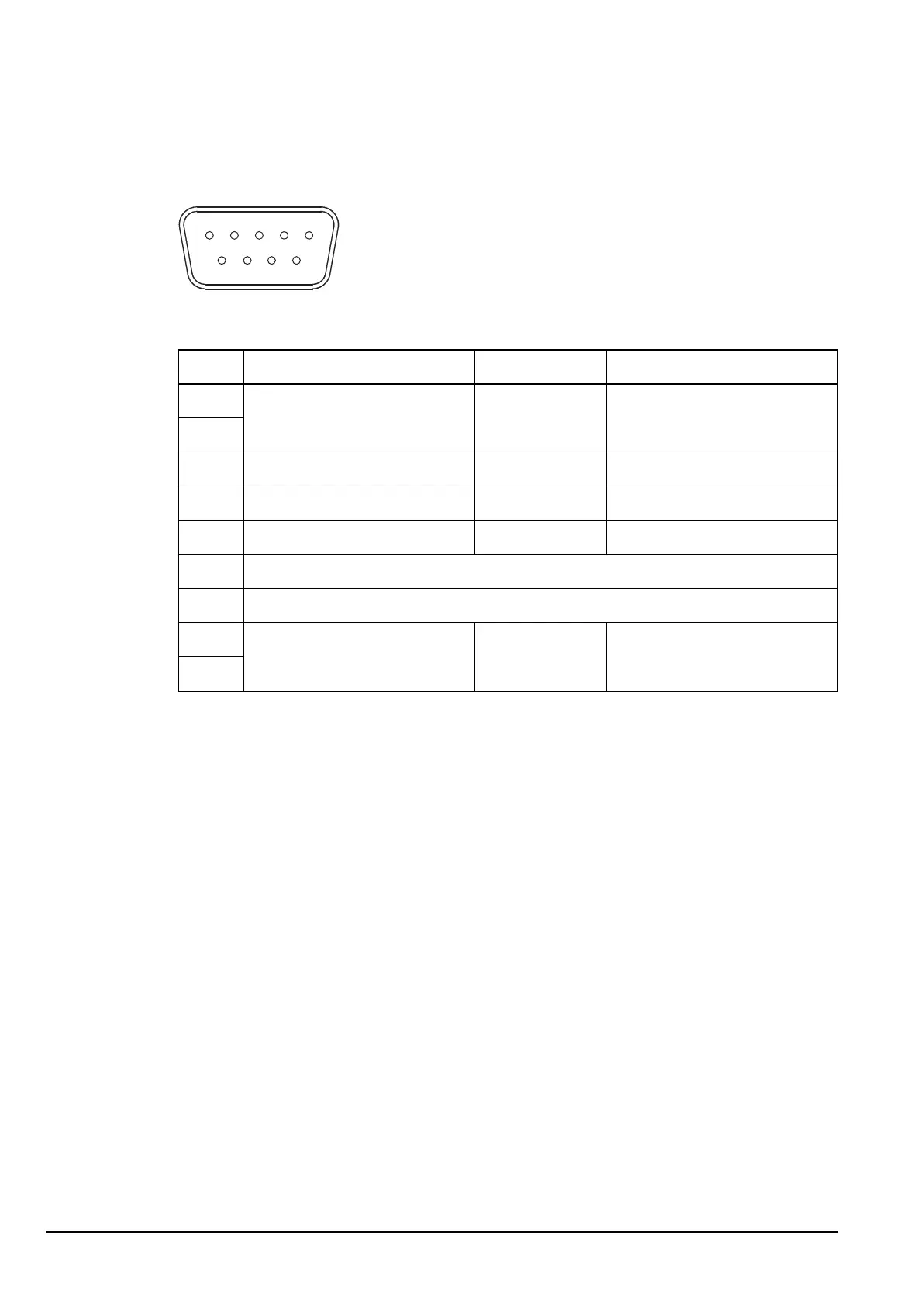
Pinouts of the ATU connector on the power amplifier
Figure 4: Front view of the ATU connector on the power amplifier
Table 2: Pinouts of the ATU connector on the power amplifier
Pin no. Function Input/output Signal level
1 A rail Output 13.6 V nominal
2
3 Spare Input/output Logic level I/O
4 Tuner reset (scan) Output 0 V = reset
5 Spare Output Active low
6N/C
7N/C
8 Ground 0 V
9
9
5
6
1