NGT—Checks and adjustments
NGT Transceiver System Technical Service Manual 147
Voltage regulators
None of the voltage regulators are adjustable. However, the output voltages can be
checked.
Handset voltages
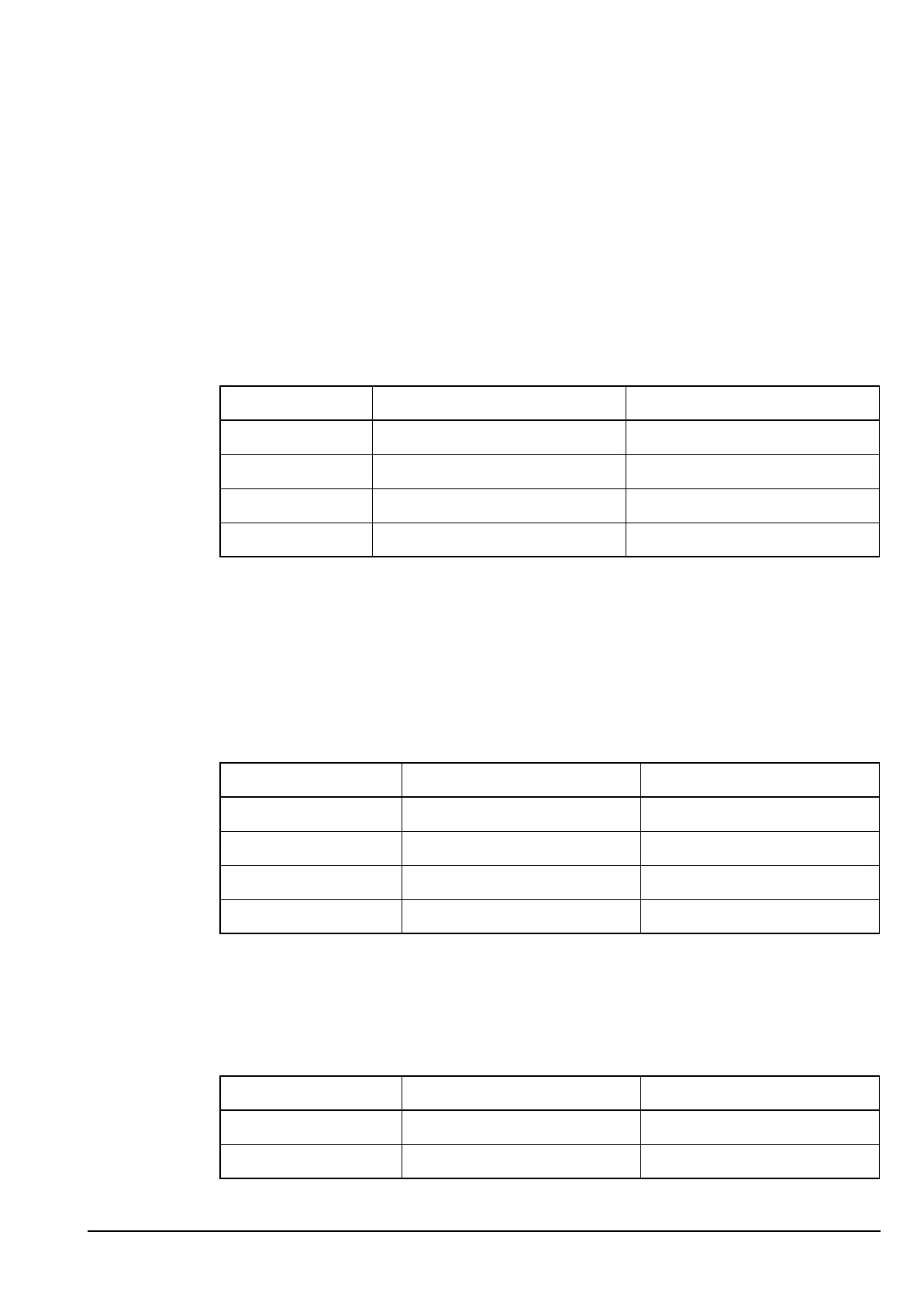
The supply voltages for the handset are shown in Table 34.
Junction box voltages
The supply voltages for the junction box are shown in Table 35 and Table 36.
Drawing 08-05300
Table 34: Supply voltages for the Handset PCB in the handset
Supply Description Source
Standby +5.4 V when transceiver is off ext
Handset power +9.2 V when transceiver is on ext
+5 V +5 V regulated supply IC10
–9 V –9 V for IC7 IC5
Drawing 08-05470 or 08-05986 (sheet 1)
Table 35: Supply voltages for the Audio PCB in the junction box
Supply Description Source
A (protected) Unregulated battery supply ext from RF unit
+10 V +10 V regulated supply IC12
+5 V +5 V regulated supply IC13
+5 VQ +5 V quiet for opamp bias IC13 (filtered)
Drawing 08-05317
Table 36: Supply voltages for the Microprocessor PCB in the junction box
Supply Description Source
+5 V +5 V digital supply IC13
A (protected) Unregulated battery supply from RF unit