NGT—Overview and specifications
48 NGT Transceiver System Technical Service Manual
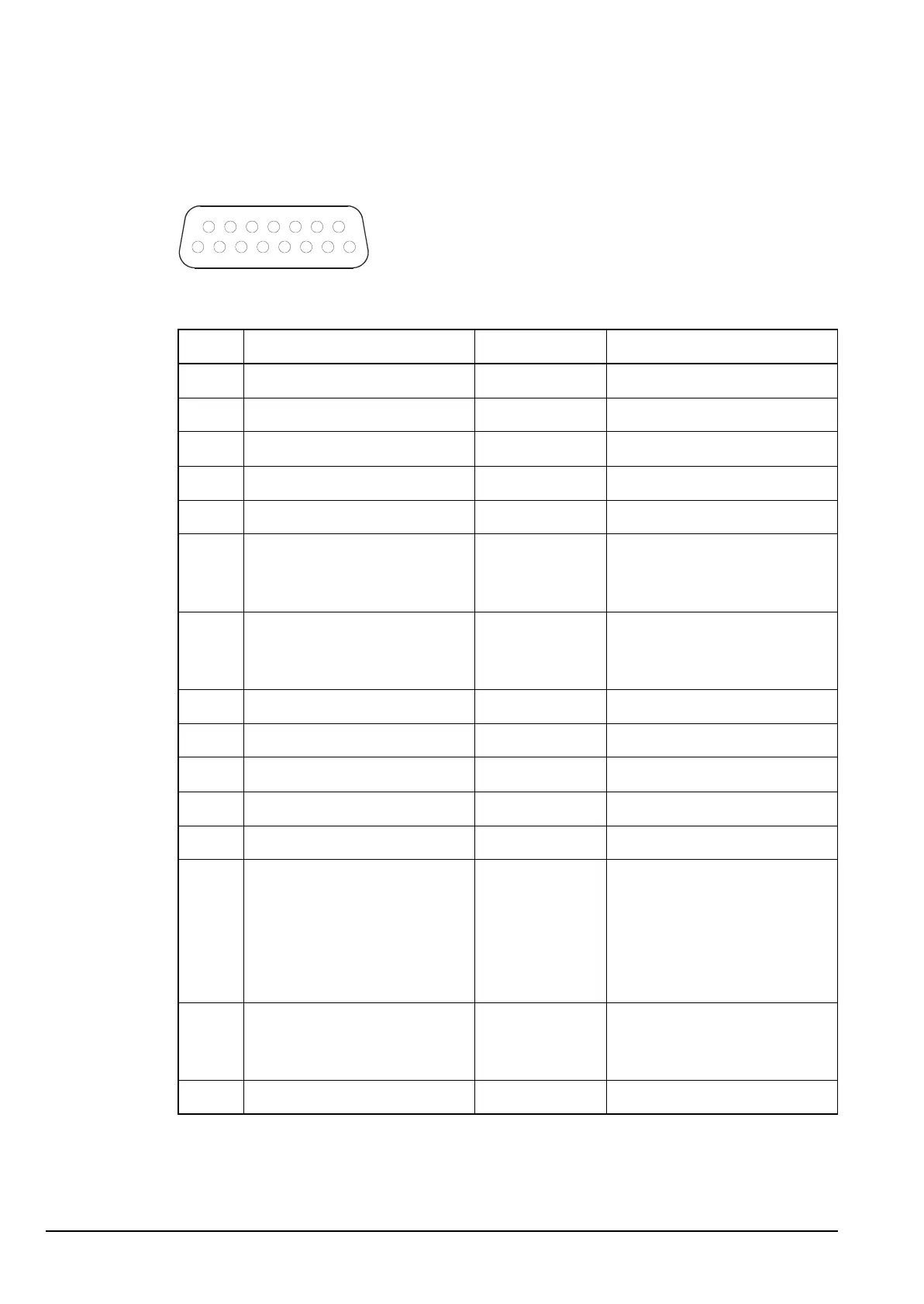
Pinouts of the 15-way GPIO connector on the RF unit (2012 only)
Figure 13: Front view of the 15-way GPIO connector on the RF unit (2012 only)
Table 11: Pinouts of the 15-way GPIO connector on the RF unit (2012 only)
Pin no. Function Input/output Signal level
1 RTS Output RS232
2 RS232 Receive data Input RS232
3 RS232 Transmit data Output RS232
4 Ground 0 V
5 Tx audio (10 kΩ balanced) Input 300 mV p–p ALC threshold
6 External alarm relay contact
(NO or NC depending on
jumper P10)
Contacts rated 50 V, 1 A
7 External alarm relay
common, or 600 Ω balanced
audio
Output Contacts rated at 5 V, 1 A, or
600 Ω audio output
8 A rail protected Output +13.6 V nominal
9 CTS Input RS232
10 PTT Input 5 V TTL logic active low
11 Morse Input 5 V TTL logic active low
12 Busy Output 5 V TTL logic
13 Quiet (Q) line Input 5 V TTL logic active high
when Fax/Data mode
selected
5 V TTL logic active low
when all other modes
selected
14 System audio unbalanced, or
600 Ω balanced audio
Output 100 Ω audio output 1 V p–p,
or 600 Ω balanced audio
output
15 Tx audio (10 kΩ balanced) Input 300 mV p–p ALC threshold
NOTE The 600 Ω output option is selected by internal links (pins 7 and 14).
1
915
8