15-10509-001
Configuring the Interface Line Links
The interface circuits on the backplane can be set up for two or four line connections.
(The interface is set up at the factory for the appropriate number of lines, either 2-wire or
4-wire interface units).
If four lines are required, an additional dual line equalisation card (CODAN part no.
08-03905-002) can be fitted, allowing up to two more lines (refer CODAN drawing
08-05994). Unused lines should be disabled to prevent signal interference.
Refer tables 1 & 2 for correct link configurations.
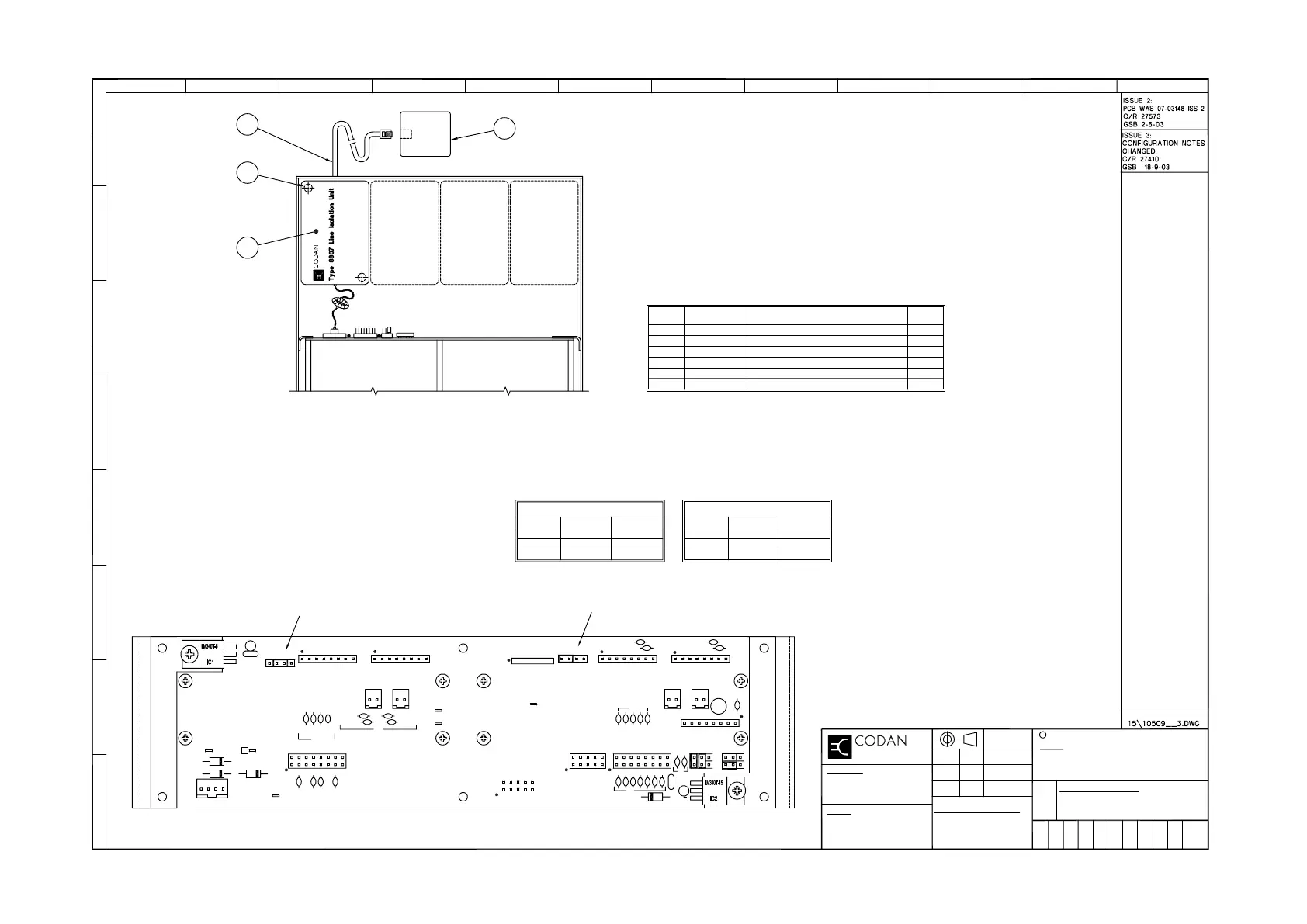
The lines are disabled by a link on the interface backplane PCB assembly 08-05995, as
shown in the Backplane View (below).
Lines one and two can be disabled by a link fitted to connector P6.
Lines three and four (if fitted) can be disabled by a link fitted to connector P105.
Note: The card is normally set up in the factory. You will only need to alter this if you add or
remove lines.
1N4004
P7
D2
1N4004
D1
0V
1N4004
J101
5V
1a
D3
A
J1
1a
1OOn
C13
+
2u2
C14
1n
C8
C7
1n
C5C4
1n 1n
C104
Line 4
C103
07-01348-03
C3
C6
C2
C1
P1
1n
4W Link 4
P103
1n
Line 3
C101
C102
P102
4W Link 3
P104 P101
300 Hz Detect Bus
Tx Audio Bus
Rx Audio Bus
1a
1a
J2
J301
P302
3k3 x 5
R1
C16
2u2
C302 --- C314
1n
1N4004
D4
C15
100n
1n
P304
P306
C313
P301
C307
C305
C303
C301
1n
C309
C311
Line 2
4W Link 2
P4
C11
C12
P5
1n
1n
L301
P303
P307
P305
Line 1
C315
1n
4W Link 1
P2
C10
C9
P3
1n
08-03993
2
1
08-04644-001
LINE
2
LINE
3
3
2
4
LINE
4
SOCKET, 6 WAY MODULAR WALL MOUNT
SCREW, M3x12
DESCRIPTION
FITTING INSTRUCTIONS
LINE ISOLATION UNIT SINGLE CH
CABLE, 6 WAY
PART No.
60-00063-501
31-23012-582
15-10509-001
08-04146-001
08-03816-001
4
1
3
2
5
ITEM
PARTS LIST
1
1
1
2
QTY
P105
P6
NONE
LINE 1
LINE 2
DISABLED
LINES 1 & 2
LINE 1
LINE 2
ENABLED
TABLE 1
CONNECTOR P6
2-3
1-2
3-4
JUMPER PINS
CONNECTOR P105
ENABLED
LINES 3 & 4
LINE 3
LINE 4
TABLE 2
JUMPER PINSDISABLED
LINE 4
LINE 3
NONE 2-3
3-4
1-2
BACKPLANE VIEW
43
21
4321
DETAIL A
1
CABLE08-042846 1
*
*
* ITEMS 5 & 6 ARE SUPPLIED AS PART OF THE KIT AND ARE NOT SHOWN.
Fitting the Line Isolation Unit
(Refer to Detail A)
1. Remove 4 screws securing top and bottom covers on the 8571 Remote Control Interface and remove the covers.
2. If converting from an existing 4W configuration to a 2W configuration, remove 4 screws securing 4 wire interface
PCB assembly to chassis on appropriate line position. Disconnect loom from RCI backplane and withdraw unit.
Remove loom connector from Line X position of rear panel (where X is 1 - 4).
3. Fit type 8807 Line Isolation Unit 08-03816-001 to chassis with 2 screws.
4. Fit connector to Line X Position on RCI backplane corresponding to line being fitted.
5. Ensure line disable link(s) are in place on backplane PCB corresponding to number of lines fitted. (In accordance
with the Configuring the Interface Line Links instructions.
6. Fit top and bottom covers to 8571 Remote Control Interface and replace screws.
FINISH
MATERIAL
OPTION 2W 8571 (NGT)
FITTING INSTRUCTIONS
15-10509-001
3
1
1
GC
1-11-02
GSB 5/11/02
AJC 29-4-03
±0.20
REFER TO NOTES
G
H
C
D
E
F
DIMENSIONS IN mm
A
B
1 2 3 4 5 6 7 8
CODAN LIMITED, A.C.N. 007 590 605: 2002
DRAWING/DOC NO.
TOLERANCES
2 PLACES DEC.
UNLESS OTHERWISE STATED
0 PLACE DEC.
1 PLACE DEC.
DRN
APPD
CHKD
±0.5
±1
A2
ISS
SCALE
DATE
TITLE
C
OF
SHT.
FILE No.
9 10 11 12