NGT—Checks and adjustments
NGT Transceiver System Technical Service Manual 151
ALTERNATIVE TEXT
Drawing 08-05889 (sheet 1)
NOTE If the PCB issue status is -06 or earlier, see drawing 08-05889 (sheet 1).
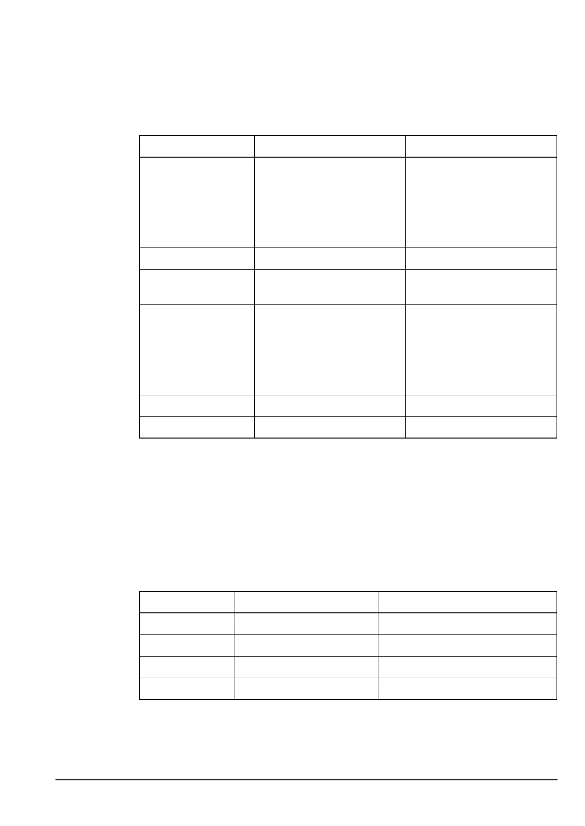
Table 44: Supply voltages for the RF/IF PCB in the RF unit (08-05889)
Supply Description Source
A Unregulated battery supply via Audio Interface PCB
(2010), or
Audio & Interconnect PCB
(2011), or
Audio Interconnect & Data
I/O PCB (2012)
+5 V +5 V regulated supply IC210
+26 V +26 V from charge pump
supply
IC402
+10 V +10 V regulated supply via Audio Interface PCB
(2010), or
Audio & Interconnect PCB
(2011), or
Audio Interconnect & Data
I/O PCB (2012)
+10 VRx +10 V In Rx V415, V416
+10 VTx +10 V In Tx V417, V418
ALTERNATIVE TEXT
Drawing 08-05415 or 08-05511 (sheet 1) and drawing 08-05416, or
Drawings 08-05869 (sheet 2) and 08-05910 (sheet 1), or
Drawings 08-06461 (sheet 2) and 08-05910 (sheet 1)
NOTE If the PCB issue status is -04 or earlier, see drawing 08-05910 (sheet 1).
Table 45: Supply voltages for the PA PCB and Filter and Control PCB in the
RF unit
Supply Description Source
A Unregulated battery supply external battery or power supply
+10 VA +10 V regulated supply IC1
+5 VA +5 V regulated supply IC4
+5 V +5 V regulated supply IC200