NGT—Checks and adjustments
154 NGT Transceiver System Technical Service Manual
Accessing Service mode
To put the transceiver into Service mode:
1 Switch off the transceiver.
1 Access the appropriate PCB.
1 Insert:
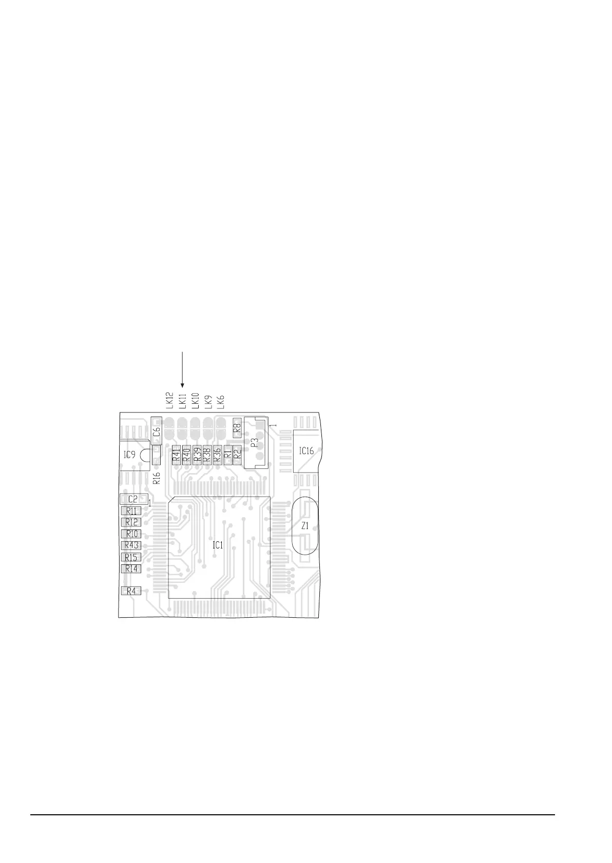
• link 11 on the Microprocessor PCB in the junction box (see drawing 08-05317
and Figure 25), or
• link A on the Application Processor Handset I/F 3 V PCB in the 2011 (see
drawing 08-05987 and Figure 26 on page 155)
• link A on the Application Processor Handset & Data I/F PCB in the 2012 (see
drawing 08-06260 and Figure 27 on page 155)
Figure 25: Position of link 11 on the Microprocessor PCB in the junction box
Service mode link