NGT—Checks and adjustments
168 NGT Transceiver System Technical Service Manual
1 Select any other channel to stop the sweep test.
Aligning the Tx filter
To align the 45 MHz Tx filter:
1 Connect the Tx exciter output on the RF/IF PCB in the RF unit to channel 1 of an
oscilloscope terminated with 50 Ω.
1 Set the channel 1 input to AC at 100 mV per division.
1 Set the timebase of the oscilloscope to 5 ms per division.
1 Connect the TRIG test point on the RF/IF PCB to the external trigger of the
oscilloscope.
1 Set the oscilloscope for an external positive trigger and adjust for lock.
1 Set the transceiver to channel 5 to initiate the transmit sweep test.
1 Adjust the trace to the centre position.
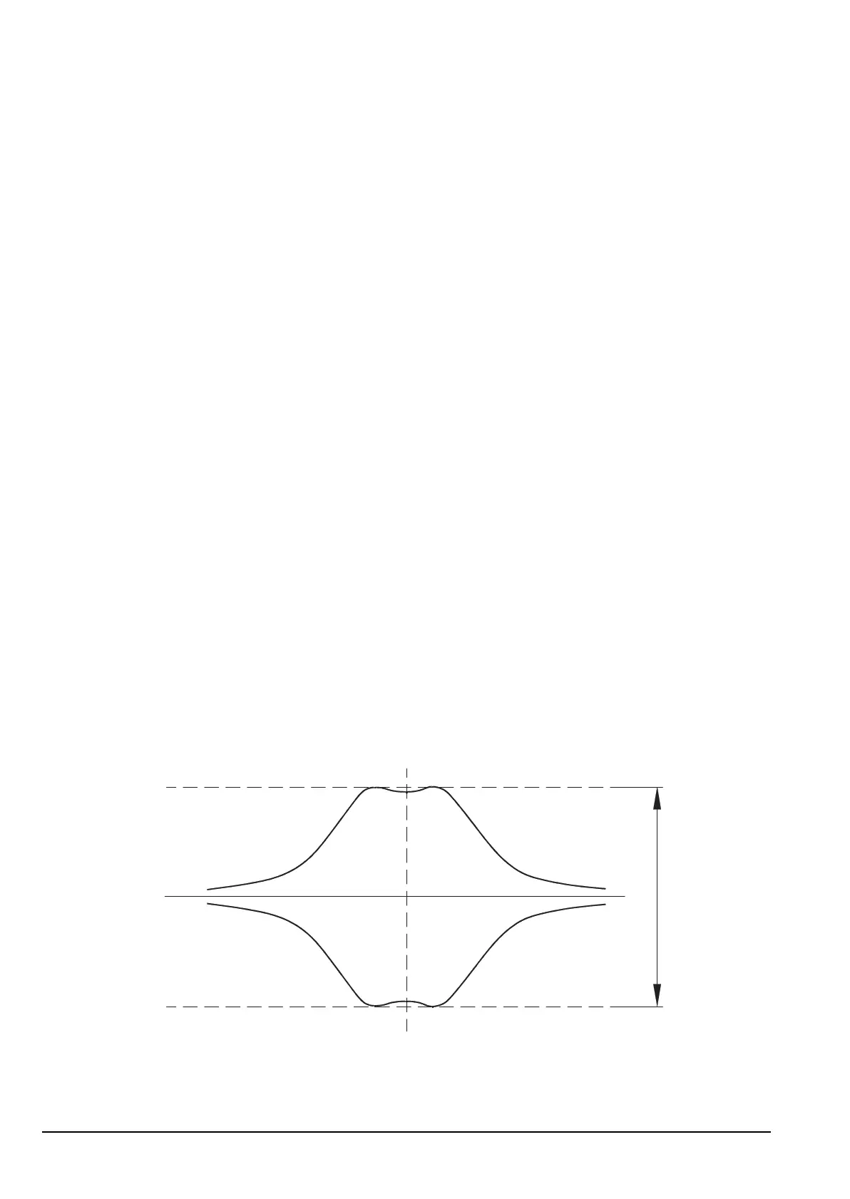
1 Adjust T107, L117 and T108 for a flat response as shown in Figure 39.
Figure 39: Transmit sweep test display
1 Select any other channel to stop the sweep test.
ALTERNATIVE TEXT
Drawing 08-05261 (sheet 2) or 08-05889 (sheet 2)
NOTE If the PCB issue status is -06 or earlier, see drawing 08-05889 (sheet 2).
NOTE
The transceiver must be in Service mode to perform this check (see
page 154, Accessing Service mode).
NOTE
The amplitude depends on the setting of the preset carrier level
potentiometer R217.
400 mV
Approx