NGT—Technical description (2010)
74 NGT Transceiver System Technical Service Manual
ALTERNATIVE TEXT
Drawing 04-03378 (sheet 1)
NOTE If the PCB issue status is -06 or earlier, see drawing 04-03378 (sheet 1).
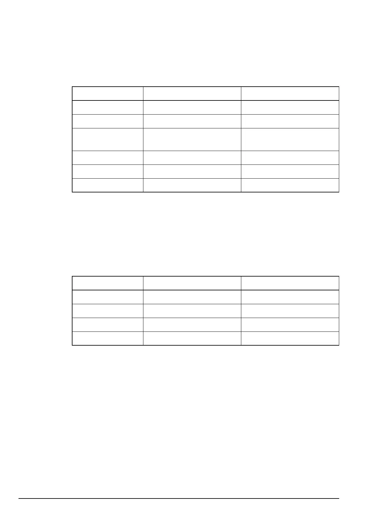
Table 24: Supply voltages for the RF/IF PCB in the RF unit (04-03378)
Supply Description Source
A Unregulated battery supply via Audio Interface PCB
+5 V +5 V regulated supply IC210
+26 V +26 V from charge pump
supply
IC402
+10 V +10 V regulated supply via Audio Interface PCB
+10 VRx +10 V In Rx V415, V416
+10 VTx +10 V In Tx V417, V418
ALTERNATIVE TEXT
Drawing 04-03169, or
Drawing 04-03369, or
Drawing 04-03542
Table 25: Supply voltages for the PA PCB and Filter and Control PCB in the RF
unit (04-03169 or 04-03369 or 04-03542)
Supply Description Source
A Unregulated battery supply ext
+10 VA +10 V regulated supply IC1
+5 VA +5 V regulated supply IC4
+5 V +5 V regulated supply IC200