NGT—Technical description (2011/2012)
106 NGT Transceiver System Technical Service Manual
Supply voltages
Handset
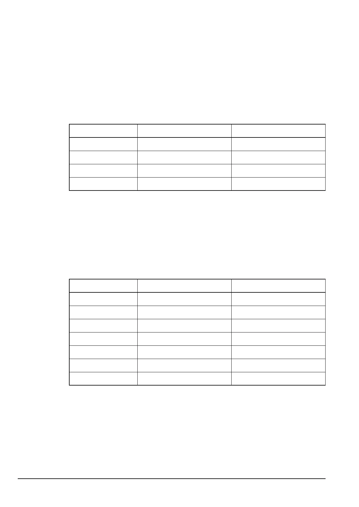
The supply voltages for the handset are shown in Table 26.
RF unit
The supply voltages for the RF unit are shown in Table 27 to Table 32.
Drawing 04-03125
Table 26: Supply voltages for the Handset PCB in the handset
Supply Description Source
Standby +5.4 V when transceiver is off ext
Handset power +9.2 V when transceiver is on ext
+5 V +5 V regulated supply IC10
–9 V –9 V for IC7 IC5
Drawing 04-03425
Table 27: Supply voltages for the Audio & Interconnect PCB in the RF unit
(2011 only)
Supply Description Source
A Unregulated battery supply via Filter and Control PCB
A (protected) 2 A current-limited battery F1
+10 V +10 V regulated supply via Filter and Control PCB
+5 V +5 V regulated supply IC7
+2.5 VQ +2.5 V quiet for opamp bias IC7 (filtered)
+5 VQ +5 V quiet for opamp bias IC7 (filtered)
+5 VSBY +5.4 V standby for handset D3, D4